Road-railway concrete transporting tank truck

A road-rail dual-use and concrete technology, which is applied to rail and road dual-use vehicles, motor vehicles, transportation and packaging, etc., can solve the problems of tank capacity limitation, inability to meet, and increase the cost of winch transportation, and achieve operational flexibility. The effect of good, strong practicability and high road adaptability

Inactive Publication Date: 2018-01-23
ZHUZHOU XUYANG ELECTRICAL & MECHANICAL TECH DEV CO LTD +1
View PDF10 Cites 9 Cited by
  • Summary
  • Abstract
  • Description
  • Claims
  • Application Information

AI Technical Summary

Problems solved by technology

[0007] 3. CN201457199U, relates to a concrete transportation equipment, specifically a rail-type concrete mixer truck, which solves the problem that the existing rail-type concrete mixer truck is used for the lining construction of a curved inclined shaft with a large inclination angle due to the limited capacity of the tank and the impact on the lining. Construction progress, increase in winch transportation costs, etc., including the tank body and the feed port and discharge port set at one end of the tank body. The frame is provided with a shuttle groove, the shuttle groove is composed of a fixed section and an adjustable section, the fixed section is erected on the frame through the front support and the rear support fixed on the frame, one end of the fixed section is located below the discharge port, and the other end is Articulates with adjustable section protruding from the frame
[0008] The concrete tank trucks in the above existing patents cannot meet the requirements of running on tracks, roads and tunnel tube surfaces, and cannot meet the construction requirements of concrete transportation in tunnels

Method used


Image

  • Road-railway concrete transporting tank truck
  • Road-railway concrete transporting tank truck
  • Road-railway concrete transporting tank truck

Examples


Embodiment Construction

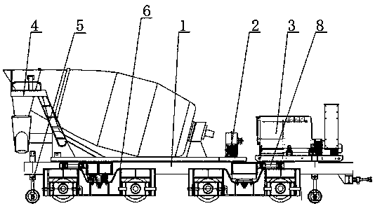
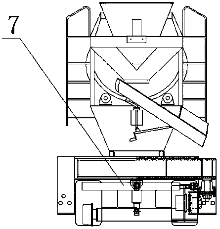
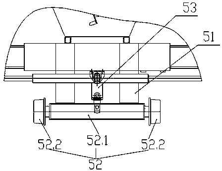
[0036] The following will be attached Figure 1~6 The present invention is further described with examples.

[0037]Concrete delivery tanker for road and rail, including frame 1, hydraulic system 2 for transmitting hydraulic power to various parts in the tanker, diesel power system 3 for providing kinetic energy for hydraulic system 2, concrete mixing tank 4 installed on frame 1, The guide steel wheel device 5 installed at the bottom of the vehicle frame 1 and can extend vertically to cooperate with the rail, the tire running device 6 installed at the bottom of the vehicle frame 1 for driving the tanker on the road, and the horizontally arranged and retractable wheel frame The expansion device 7 and the hydraulic steering device 8 are characterized in that the front and rear ends of the bottom of the vehicle frame 1 are equipped with a guide steel wheel device 5 and a wheel frame expansion device 7, and both ends of the wheel frame expansion device 7 are equipped with winding ...


PUM


Abstract

The invention discloses a road-railway concrete transporting tank truck. The tank truck comprises a truck rack, a hydraulic system which transmits hydraulic power for all parts in the tank truck, a diesel power system which provides kinetic energy for the hydraulic system, a concrete stirring tank on the truck rack, guide steel wheel devices which are mounted on the bottom of the truck rack and can extend out in the vertical direction to be matched with a rail, tire walking devices which are mounted on the bottom of the truck rack and used for driving the tank truck to walk on road surface, wheel rack telescopic devices which are horizontally arranged and can stretch and hydraulic steering devices. The guide steel wheel devices and the wheel rack telescopic devices are arranged at both thefront end and the back end of the bottom of the truck rack, the tire walking devices which can rotate around the vertical direction are mounted at two ends of each wheel rack stretching device, and the hydraulic steering devices are arranged between the truck rack and the tire walking devices; the hydraulic steering devices stretch and drive the tire walking devices to rotate around the verticaldirection, and thus steering of the truck body is achieved. The road-railway concrete transporting tank truck can walk on a road or a railway, can also walk on a tunnel tube-shaped surface, and meetsthe construction requirement of concrete transporting in a tunnel.

Description

technical field [0001] The invention relates to a road-rail dual-purpose concrete transport tank car, which belongs to the field of concrete transport tank car manufacturing. Background technique [0002] Concrete is one of the most important civil engineering materials today. It is composed of cementitious materials, granular aggregates (also known as aggregates), water, and if necessary, admixtures and admixtures prepared in a certain proportion, uniformly stirred, densely formed, cured and hardened. artificial stone. Concrete has the characteristics of rich raw materials, low price and simple production process, so its consumption is increasing. At the same time, concrete also has the characteristics of high compressive strength, good durability, and a wide range of strength grades. These characteristics make it widely used, not only in various civil engineering, but also in shipbuilding, machinery industry, marine development, geothermal engineering, track constructio...

Claims


Application Information

Patent Timeline
Patent Type & Authority Applications(China)
IPC IPC(8): B60F1/04B28C5/42
Inventor 段启楠张明中邓建华杨永洲
Owner ZHUZHOU XUYANG ELECTRICAL & MECHANICAL TECH DEV CO LTD
Why Eureka
Try Eureka