
a smart community

A community and smart technology, applied in the field of circuits, can solve the problems of poor anti-interference and stability, signal transmission attenuation, etc., to achieve accurate transmission, improve anti-interference and stability.

Active Publication Date: 2018-08-03
CHINA CONSTR SEVENTH ENG DIVISION CORP LTD
View PDF7 Cites 0 Cited by
  • Summary
  • Abstract
  • Description
  • Claims
  • Application Information

AI Technical Summary

Problems solved by technology

[0005] In view of the above situation, in order to overcome the defects of the prior art, the purpose of the present invention is to provide a smart community, which has the characteristics of ingenious conception and humanized design, and effectively solves the attenuation, anti-interference and poor stability of signal transmission in the smart community technical issues

Method used


Image

  • a smart community
  • a smart community
  • a smart community

Examples


Embodiment 1

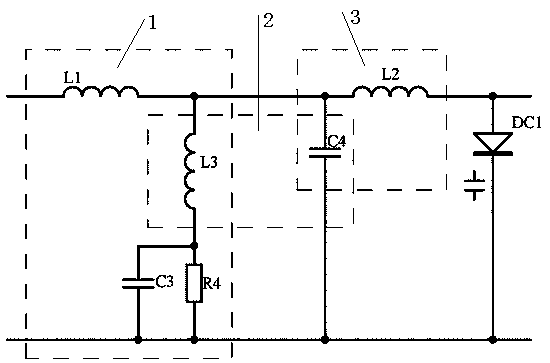
[0017] Embodiment 1, a smart community requires the transmission of various signals in the smart community, such as analog or digital electrical signals such as video signals, sound signals, and power signals in the smart community, that is, modulated signals. All need the corresponding collector to collect, after the signal processing circuit is processed, the transmitter sends the control terminal of the smart community. The signal processing circuit is for short-to-medium distance transmission, so the signal processing circuit is designed with frequency modulation circuit, signal amplification circuit and filter circuit. The frequency modulation circuit receives the signal at the signal input terminal, modulates the signal to a high frequency, and then the signal amplification circuit increases the amplitude of the signal, and finally the filter circuit filters and stabilizes the voltage and outputs it to the transmitter from the signal output terminal;

[0018] The frequenc...

Embodiment 2

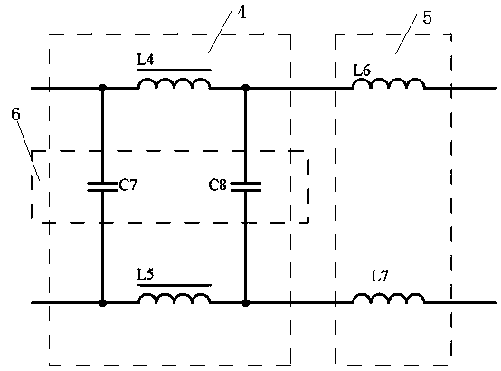
[0019] Embodiment 2, on the basis of Embodiment 1, the filter circuit is used for the parasitic interference in the frequency modulation process and the interference of external random noise, and the differential mode anti-interference circuit 4 is connected in parallel by a circuit composed of a capacitor C7 and a voltage transformer L5 in series The loop composed of voltage transformer L4 and capacitor C8 connected in series improves the differential mode anti-interference ability of the signal. The differential mode filter circuit 6 is composed of capacitor C7 and capacitor C8, which is used to filter out differential mode interference. The common mode filter circuit 5 is composed of inductors L6 and L7 are connected in parallel. The inductance presents an inductance to the common mode between the external random noise and the ground, and effectively absorbs the common mode interference. Finally, after the voltage regulator diode DZ1 is reversed and stabilized, the final proc...

Embodiment 3

[0020] Embodiment 3, on the basis of Embodiment 1 or 3, the frequency modulation circuit is used to modulate the signal at the signal input end into a high-frequency signal. Specifically, the analog or digital electrical signal at the signal input end is coupled through capacitor C1, resistor The R1 bias is added to the base of the transistor Q1, and the emitter of the transistor Q1 is respectively connected to one end of the bypass capacitor C2 and one end of the emitter resistor R2 for amplification, and the output from the collector of the transistor Q1 is connected to the first resonant circuit 1 The resonant frequency is generated and modulated into a high-frequency signal, and any parameter in the first resonant circuit 1 can be changed to adjust the resonant frequency, that is, to adjust the frequency of the high-frequency signal.


PUM


Abstract

A kind of smart community, in which various signals need to be transmitted in the smart community, the analog or digital electric signal of the basic environment in the smart community collected, that is, the modulated signal, and the resonant frequency generated by the first frequency modulation loop, that is, the carrier, are modulated It is a high-frequency signal, and the high-frequency signal further adjusts the modulation coefficient through the second frequency modulation circuit to generate the optimal transmission frequency required, and then increases the amplitude of the signal through the signal amplification circuit, thereby solving the problem caused by the attenuation of the signal during transmission. The problem of signal transmission distance limitation and time delay; in order to solve the parasitic interference in the frequency modulation process and the interference of external random noise, on the one hand, it is suppressed by the differential mode anti-interference circuit in the filter circuit, and on the other hand, it is suppressed by the differential mode filter in the filter circuit The circuit and common mode filter circuit filter out interference, thereby improving the anti-interference and stability, and then the transmitter sends the control terminal of the smart community to ensure the timely and accurate transmission of the signal.

Description

technical field [0001] The invention relates to the technical field of circuits, in particular to a smart community. Background technique [0002] With the rapid development of the market economy and science and technology, the economic level of urban community residents has also increased. Different groups in the community have safety precautions for the community, the intelligence of family residences, the convenience of community life, and the relationship between various groups in the community. The need for interaction, the convenience of community medical care, and the special services for the elderly and children in the community have higher requirements. Based on this situation, a new concept of smart community has emerged, which is a new model of social management innovation under the new situation. Smart community refers to the integrated application of the new generation of information technology such as the Internet of Things, cloud computing, and mobile Internet...

Claims


Application Information

Patent Timeline
Patent Type & Authority Patents(China)
IPC IPC(8): H04L27/12H04L27/16H03H7/09
Inventor 侯涛冯大阔张中善陈璐郑培君曹江涛
Owner CHINA CONSTR SEVENTH ENG DIVISION CORP LTD
Learn More