Automatic spraying conveying device on annular casting production line

A technology of automatic spraying and conveying device, applied in the direction of spraying device, liquid spraying device, etc., can solve the problems of large occupation area of ​​production line and troublesome cooperation and installation relationship, and achieve the effect of small occupation area

Inactive Publication Date: 2018-01-26
十堰市宏昌达工贸股份有限公司
View PDF0 Cites 1 Cited by
  • Summary
  • Abstract
  • Description
  • Claims
  • Application Information

AI Technical Summary

Problems solved by technology

[0003] Based on the above, the present inventors found that the existing spraying and conveying equipment and devices after casting are often of ordinary conveyor belt structure, and the transmission mode mostly adopts belt transmission or chain transmission, and the coordination

Method used


Image

  • Automatic spraying conveying device on annular casting production line
  • Automatic spraying conveying device on annular casting production line
  • Automatic spraying conveying device on annular casting production line

Examples


Embodiment

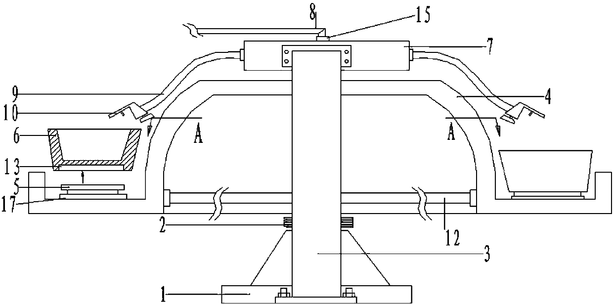
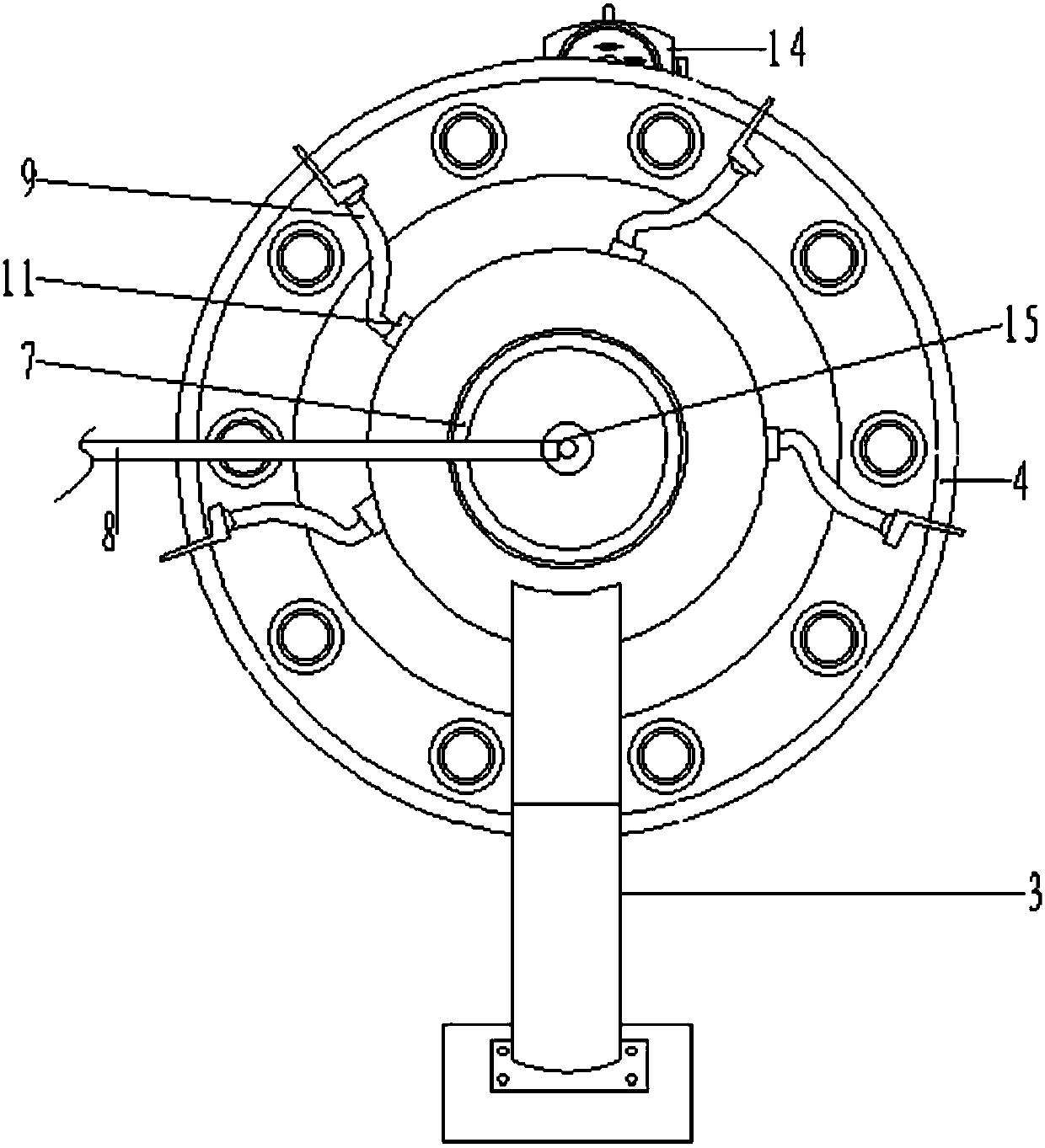
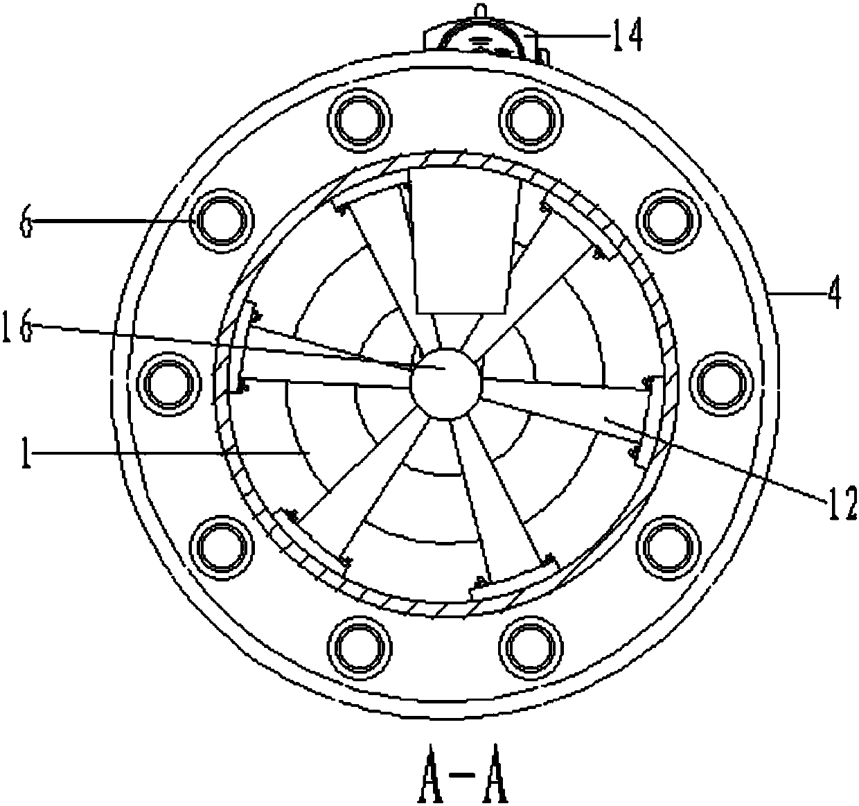
[0023] as attached figure 1 As shown in Attachment 4:

[0024] The present invention provides an automatic spraying conveying device on an annular casting production line, comprising a base 1, a pulley 2, a support arm 3, a spraying conveying seat 4, a bearing 5, a spraying cabin 6, an air collecting cabin 7, an air intake pipe 8, a spraying pipe 9, Spray gun 10, first rubber pipe inlet chuck 11, connecting rod 12, installation groove 13, slow motor 14, second rubber pipe inlet chuck 15, rotating shaft 16 and bearing support seat 17, the base 1 is a disc Shaped structure, its top surface is vertically installed with a rotating shaft 16 through the bearing seat, and the rotating shaft 16 is connected to the slow motor 14 installed on the outside through the belt through the pulley 2 installed on the shaft wall, and the slow motor 14 It is electrically connected with an external power supply; six connecting rods 12 are installed radially and uniformly on the shaft wall of the r...


PUM


Abstract

The invention provides an automatic spraying conveying device on an annular casting production line. The automatic spraying conveying device comprises a low-speed motor, a second rubber inlet pipe clamping head, a rotating shaft and bearing supporting seats; a base is of a disc-shaped structure, the rotating shaft is perpendicularly mounted on the top face of the base through the bearing seats, and the rotating shaft and the low-speed motor mounted on the outer side of the rotating shaft are in transmission connection through a belt wheel mounted on the shaft wall of the rotating shaft and a belt; six connecting rods are radially mounted on the shaft wall of the rotating shaft in a uniformly distributed mode; a gas inlet pipe and four spraying pipes are mounted in the top face and the annular periphery of a gas collection compartment through the penetrating second rubber inlet pipe clamping head and four penetrating first rubber inlet pipe clamping heads in a penetrating mode correspondingly, wherein spraying guns are mounted at the pipe heads of the spraying pipes correspondingly; a spraying compartment is of an inverted-cone-shaped cavity type structure and supported and connected by bearings and accordingly can rotate by 360 degrees, thus, a worker can conduct spraying work on a workpiece in multiple directions conveniently, and using is more flexible.

Description

technical field [0001] The invention belongs to the technical field of conveying devices, in particular to an automatic spraying conveying device on a circular casting production line. Background technique [0002] Casting production in mechanical production often requires the use of casting machines or other casting equipment to shape the workpiece by pouring liquid into the casting mold. After the molding is rough and finished, the surface is polished, and then the surface is colored and sprayed until a standard shape is produced. Product pieces, and the spraying link in this process is very important. [0003] Based on the above, the present inventors found that the existing spraying and conveying equipment and devices after casting are often of ordinary conveyor belt structure, and the transmission mode mostly adopts belt transmission or chain transmission, and the coordination and installation relationship involved is relatively troublesome. And it is often only a simp...

Claims


Application Information

Patent Timeline
IPC IPC(8): B05B13/02B05B9/04
Inventor 胡玉梅胡军
Owner 十堰市宏昌达工贸股份有限公司
Why Eureka
Try Eureka