
Heat pump system and control method thereof

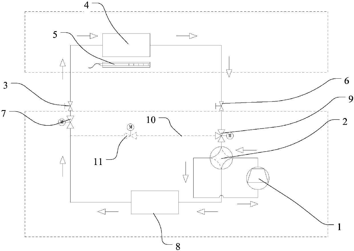
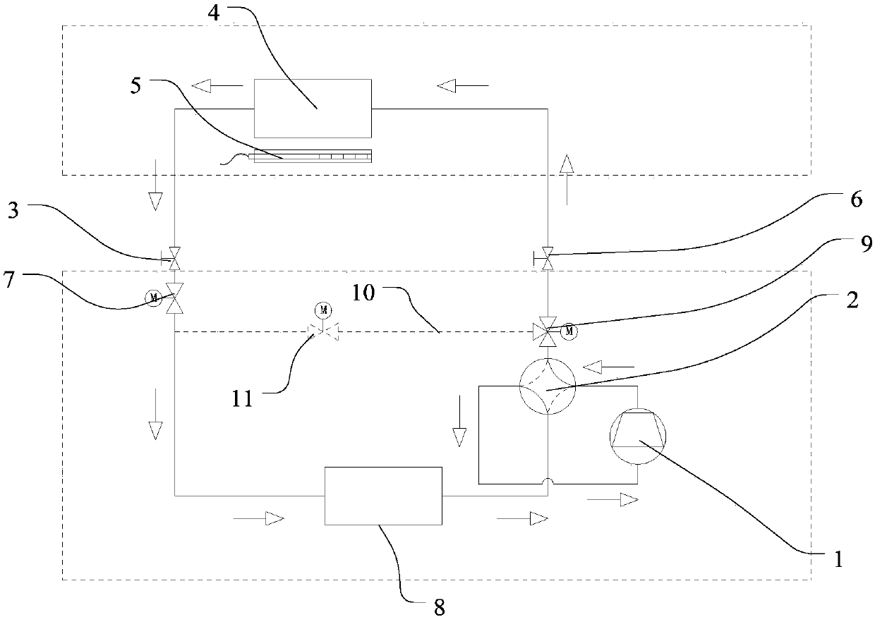
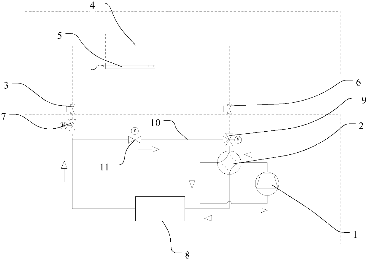
A technology of heat pump system and heating mode, which is applied in the defrosting field of air conditioners, which can solve the problems of prolonging the defrosting time, reducing the heat of defrosting, and existing safety hazards, so as to achieve the best defrosting effect, improve heat exchange efficiency, and ensure comfort sexual effect

Pending Publication Date: 2018-01-26
GREE ELECTRIC APPLIANCES INC
View PDF13 Cites 10 Cited by
  • Summary
  • Abstract
  • Description
  • Claims
  • Application Information

AI Technical Summary

Problems solved by technology

The reason is that when the refrigeration cycle defrosts, the indoor heat exchanger acts as an evaporator, and condensation water will be generated on the surface of the indoor heat exchanger. If the auxiliary heating device and the internal fan are turned on, the condensation water on the surface of the indoor heat exchanger will be blown by the internal fan It may fall on the auxiliary heating device, so there is a potential safety hazard. In addition, in this defrosting mode, the air blowing out of the room is a mixture of cold and hot air, which affects the user's comfort; when performing hot air defrosting, Although the indoor heat exchanger is not an evaporator, there is no safety hazard when the auxiliary heating device and the internal fan are turned on, but when the internal fan is running, the heat in the system will be blown into the room through the evaporator, reducing the heat used for defrosting and prolonging defrosting time, reducing the reliability of defrosting

Method used


Image

  • Heat pump system and control method thereof
  • Heat pump system and control method thereof
  • Heat pump system and control method thereof

Examples


Embodiment Construction

[0058] The present invention is described below based on examples, but the present invention is not limited to these examples. In the following detailed description of the invention, some specific details are set forth in detail. The present invention can be fully understood by those skilled in the art without the description of these detailed parts. To avoid obscuring the essence of the present invention, well-known methods, procedures, procedures, and components have not been described in detail.

[0059] Additionally, those of ordinary skill in the art will appreciate that the drawings provided herein are for illustrative purposes and are not necessarily drawn to scale.

[0060] Unless the context clearly requires, throughout the specification and claims, "comprises", "comprises" and similar words should be interpreted in an inclusive sense rather than an exclusive or exhaustive meaning; that is, "including but not limited to" meaning.

[0061] In the description of the ...


PUM


Abstract

The invention discloses a heat pump system and a control method for the heat pump system. A cold medium flowing loop of the heat pump system is provided with a compressor, an outdoor heat exchanger, an indoor heat exchanger and a throttling device, and the heat pump system further comprises an indoor assistant heating device and a bypass branch loop. The indoor assistant heating device is used forperforming assistant heating when the heat pump system runs in a defrosting mode, and when the heat pump system runs in the defrosting mode, the indoor assistant heating device runs and performs heating; and the bypass branch loop together with the compressor and the outdoor heat exchanger form a defrosting loop, a cold medium discharged by the compressor is made not flow through the indoor heatexchanger but enters the outdoor heat exchanger to perform defrosting. According to the heat pump system and the control method for the heat pump system provided by the invention, the cold medium doesnot flow through the indoor heat exchanger in the defrosting mode, therefore the indoor assistant heating device can be started to perform heating on the indoor environment when the defrosting is performed, the comfort of the indoor environment in the defrosting mode is guaranteed, and the good defrosting effect can be maintained at the same time.

Description

technical field [0001] The invention relates to the technical field of air-conditioning defrosting, in particular to a heat pump system and a control method thereof. Background technique [0002] The defrosting methods of the existing heat pump air-conditioning system are mainly two methods of refrigeration cycle defrosting and hot gas defrosting. Among them, the defrosting of the refrigeration cycle is to switch the system from the heating cycle to the refrigeration cycle through the four-way reversing valve, and the hot gas defrosting is to increase the flow rate of the expansion valve under the heating cycle so that the high-temperature refrigerant enters the outdoor heat exchanger for defrosting. Neither method can heat the room during the defrosting process, which will cause the temperature of the room to drop and affect the comfort of the room. Especially in the refrigeration cycle defrosting method, the indoor heat exchanger acts as an evaporator during defrosting, w...

Claims


Application Information

Patent Timeline
Patent Type & Authority Applications(China)
IPC IPC(8): F25B13/00F25B41/06F25B47/02F25B41/34
Inventor 彭光前吴俊鸿于博车雯陈英强廖敏连彩云田雅颂翟振坤
Owner GREE ELECTRIC APPLIANCES INC
Learn More