
Heat exchange system for reducing ash accumulation and enhancing heat exchange based on corrugated heat exchange fins

A heat-exchange fin and heat-enhancing technology, which is applied in the field of heat-exchange systems based on corrugated heat-exchange fins to slow down fouling and enhance heat exchange, can solve the problems of easy fouling in the leeward area, large eddy currents in the wake area, and large resistance. , to achieve the effect of preventing ash accumulation and bridging, increasing the heat exchange area and easy operation.

Pending Publication Date: 2018-01-26
HUANENG POWER INTERNATIONAL +2
View PDF5 Cites 0 Cited by
  • Summary
  • Abstract
  • Description
  • Claims
  • Application Information

AI Technical Summary

Problems solved by technology

Round pipes are easy to manufacture and widely used, but they have high resistance, large eddy currents in the wake area, and dust accumulation on the leeward surface
The elliptical tube is based on the circular tube, and is cold-drawn through an elliptical mold. The resistance is 10% lower than that of the conventional circular tube, and the heat exchange capacity is equivalent to that of the circular tube, but there is still room for optimization in the wake area

Method used


Image

  • Heat exchange system for reducing ash accumulation and enhancing heat exchange based on corrugated heat exchange fins
  • Heat exchange system for reducing ash accumulation and enhancing heat exchange based on corrugated heat exchange fins
  • Heat exchange system for reducing ash accumulation and enhancing heat exchange based on corrugated heat exchange fins

Examples


Embodiment Construction

[0022] The present invention is described in further detail below in conjunction with accompanying drawing:

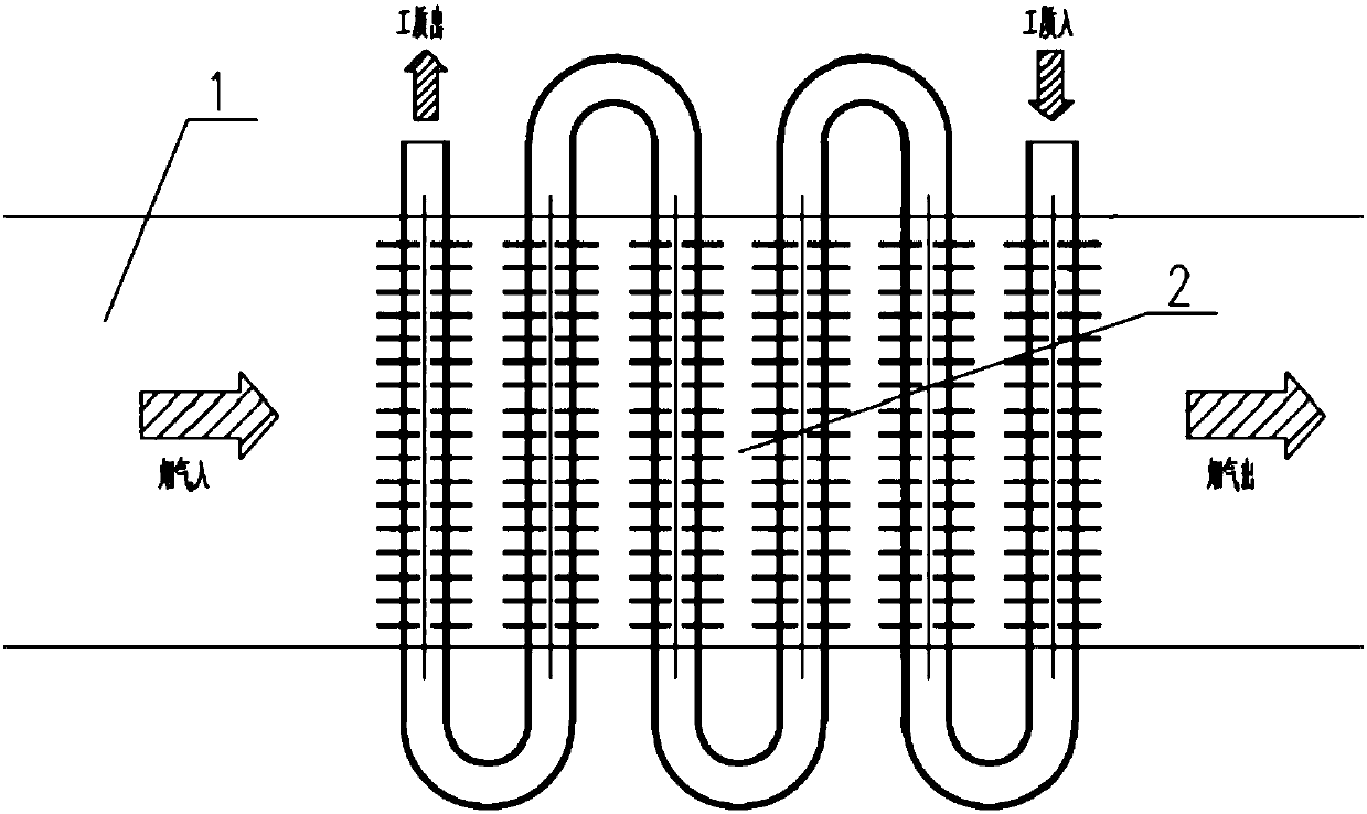
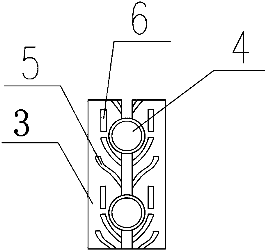
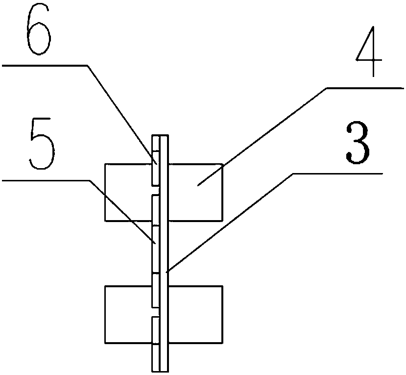
[0023] refer to figure 1 According to the present invention, the heat exchange system based on corrugated heat exchange fins to reduce dust deposition and enhance heat exchange includes a flue 1 and a heat exchanger 2, wherein the heat exchanger 2 includes a number of heat exchange base pipes 4 and a number of heat exchange fins sheet 3, each heat exchange base tube 4 is distributed in a serpentine shape, the working fluid inlet at one end of each heat exchange base tube 4 and the working medium outlet at the other end are located outside the flue 1, and the middle part of each heat exchange base tube 4 is located at In the flue 1, each heat exchanging fin 3 is located in the flue 1, and each heat exchanging fin 3 is sleeved on the outer wall of each heat exchanging base pipe 4, and each heat exchanging fin 3 is provided with a The heat-exchanging corrugations 6 and t...


PUM


Abstract

The invention discloses a heat exchange system for reducing ash accumulation and enhancing heat exchange based on corrugated heat exchange fins. The heat exchange system comprises a flue and a heat exchanger. The heat exchanger comprises multiple heat exchange base pipes and the multiple heat exchange fins. The heat exchange base pipes are distributed in a serpentine manner. A working fluid inletin one end and a working fluid outlet in the other end of each heat exchange base pipe both are located outside the flue. The middle of each heat exchange base pipe is located in the flue. All the heat exchange fins are located in the flue. The outer wall of each heat exchange base pipe is sleeved with the corresponding heat exchange fin. The side faces of all the heat exchange fins are correspondingly provided with heat exchange enhancement corrugations and anti-ash-accumulation corrugations for guiding fly ash in flue gas in the flue to weak regions of the heat exchange base pipes. By the adoption of the system, the back faces of the heat exchange base pipes are not likely to generate accumulated ash, the heat exchange effect is good, and the flue gas resistance and the vortexes in the weak regions are small.

Description

technical field [0001] The invention belongs to the technical field of heat exchange enhancement, and relates to a heat exchange system based on corrugated heat exchange fins for reducing dust deposition and enhancing heat exchange. Background technique [0002] The exhaust heat loss is the largest among all heat losses of power plant boilers, generally 5% to 8%, accounting for about 80% of the total heat loss of the boiler. With the vigorous implementation of energy saving and emission reduction policies, the utilization of waste heat from flue gas in thermal power plants has become one of the focuses of research and transformation at the present stage, and the low-temperature economizer has been widely used as the main equipment for the utilization of waste heat from exhaust gas. A heat exchanger is installed between the heater and the electrostatic precipitator to reduce the inlet smoke temperature of the electrostatic precipitator to about 90°C, and the absorbed heat can...

Claims


Application Information

Patent Timeline
Patent Type & Authority Applications(China)
IPC IPC(8): F28D7/00F28F1/08F28F1/30F28F19/00
Inventor 徐党旗白少林文成明周刚张知翔梁仕铓罗怀宇陆军邹小刚
Owner HUANENG POWER INTERNATIONAL
Learn More