
An adsorption tower for preventing ash accumulation in a gas chamber and a method for using the adsorption tower for flue gas treatment

An adsorption tower and flue gas technology, used in adsorption towers and flue gas treatment fields to prevent ash accumulation in the gas chamber, can solve the problem of accelerated agglomeration, corrosion of the bottom wall, and active coke being turned out from the grids on both sides of the bed. The bottom area of ​​the air inlet chamber and other problems can prevent the accumulation of dust and achieve the effect of preventing dust accumulation.

Active Publication Date: 2022-06-17
SINOPEC ENG +1
View PDF9 Cites 0 Cited by
  • Summary
  • Abstract
  • Description
  • Claims
  • Application Information

AI Technical Summary

Problems solved by technology

As the operation continues, the agglomeration of the bottom area of ​​the gas chamber continues to increase, which may lead to a continuous reduction in the area where the flue gas traverses the active coke bed and may prevent the flue gas from reaching the distribution grid at the bottom of the active coke bed. area, which affects the purification effect of the adsorption tower
In addition, during the operation, since the gap between the grids on both sides of the active coke bed is much larger than that of the active coke, a small amount of active coke may fall out of the grids on both sides of the bed during the movement of the active coke. In the bottom area of ​​the air chamber, because the bottom is a flat bottom structure, the active coke cannot be discharged in time in this area, and the active coke may deposit particles together, which will accelerate the agglomeration speed in this area
Moreover, because the activated coke fine powder contains adsorbed sulfuric acid, the agglomerated area may also corrode the bottom wall under the action of water vapor in the flue gas

Method used


Image

  • An adsorption tower for preventing ash accumulation in a gas chamber and a method for using the adsorption tower for flue gas treatment
  • An adsorption tower for preventing ash accumulation in a gas chamber and a method for using the adsorption tower for flue gas treatment
  • An adsorption tower for preventing ash accumulation in a gas chamber and a method for using the adsorption tower for flue gas treatment

Examples


Embodiment

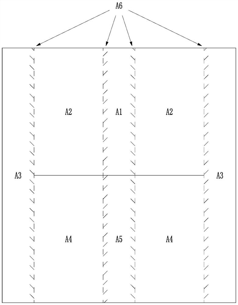
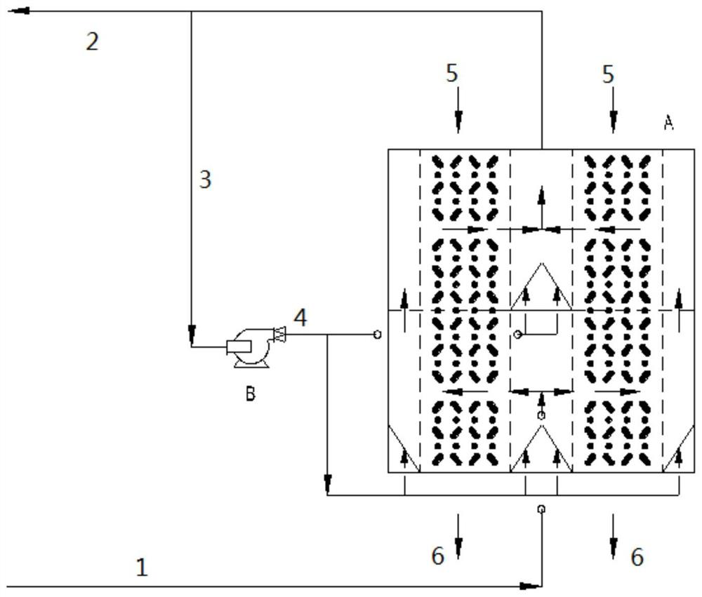
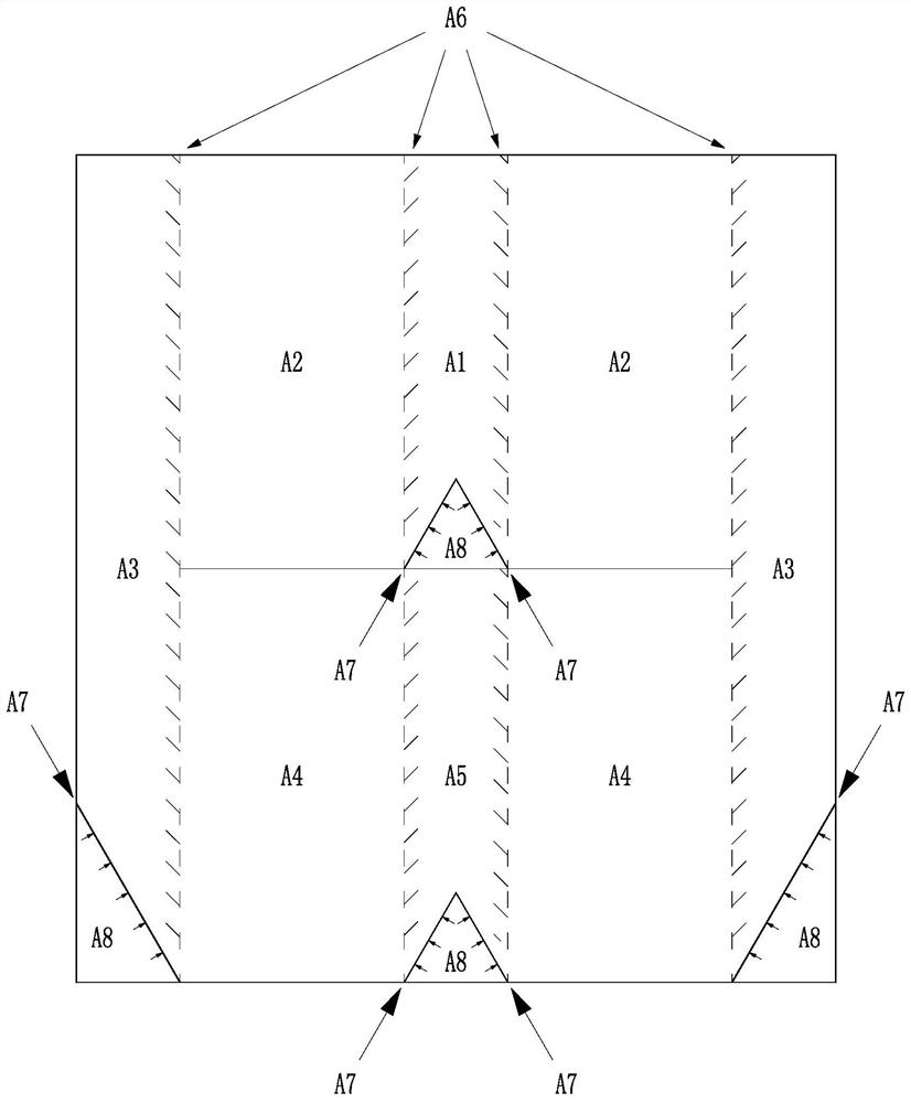
[0038] The structure of adsorption tower A used to treat flue gas is as follows image 3 As shown, the internal structure of the adsorption tower A is provided with the original flue gas inlet area A5 and the clean flue gas exit area A1 from bottom to top, and the lower section cross-flow adsorption located outside the original flue gas entrance area A5 and the clean flue gas exit area A1 respectively. Area A4 and upper cross-flow adsorption area A2, and flue gas redistribution area A3 located outside the lower cross-flow adsorption area A4 and upper cross-flow adsorption area A2;

[0039] The upper cross-flow adsorption area A2 and the lower cross-flow adsorption area A4 are penetrated by the activated coke redistribution section, and are respectively connected with the flue gas redistribution area A3 through the distribution grid. The upper cross-flow adsorption area A2 and the lower cross-flow adsorption area A4 are inside With active coke bed;

[0040] The upper section c...


PUM


Abstract

The invention belongs to the field of chemical industry, and specifically discloses an adsorption tower for preventing dust accumulation in a gas chamber and a method for using the adsorption tower to treat flue gas. The fluidized air distribution pipe is used to avoid dust accumulation and agglomeration at the bottom of each air chamber to ensure the purification effect of the adsorption tower. In the adsorption tower for preventing dust accumulation in the air chamber of the present invention, since the inclination angle of the bottom inclined plate is greater than the inclination angle of the corresponding distribution grid, and the distance between the distribution grid is relatively large, part of the particulate matter in the original flue gas and part of the broken particles After the fine powder of active coke is deposited on the inclined plate at the bottom, it is loosened by the fluidization wind on the bottom plate and then enters the active coke bed of the adsorption tower from the bottom of the distribution grid, which can effectively prevent dust accumulation in this area.

Description

technical field [0001] The invention belongs to the field of chemical industry, and more particularly relates to an adsorption tower for preventing ash accumulation in a gas chamber and a method for using the adsorption tower for flue gas treatment. Background technique [0002] The activated coke dry flue gas purification process began industrial application in the 1980s. With the increasing environmental protection requirements, the activated coke dry flue gas purification process has outstanding advantages such as high desulfurization efficiency, simultaneous removal of multiple pollutants, no water consumption in the reaction, no waste water and slag discharge, and no corrosion of system equipment. More and more attention, the application is also increasingly widespread. [0003] The reason why activated coke has the functions of desulfurization, denitration, dust removal and simultaneous removal of various pollutants is due to its porous structure and rich surface acti...

Claims


Application Information

Patent Timeline
Patent Type & Authority Patents(China)
IPC IPC(8): B01D53/12
CPCB01D53/12
Inventor 郝少博黄孟旗周桂娟韩健张喆李出和
Owner SINOPEC ENG
Learn More