Non-contact sensor circuit

A non-contact sensor and non-contact coupling technology, applied in instruments, measuring electricity, measuring electrical variables, etc., can solve the problems of unfavorable detection circuit stable operation, large output DC drift, complex circuit structure, etc., and achieves good physical realizability. , the effect of reducing output drift and simple circuit structure

Active Publication Date: 2018-01-26
南京和协集成电路科技有限公司
View PDF6 Cites 0 Cited by
  • Summary
  • Abstract
  • Description
  • Claims
  • Application Information

AI Technical Summary

Problems solved by technology

However, the effect of the input bias circuit to discharge the accumulated charge of the coupling capacitor is contradictory to the realization of the input impedance. The higher the realized input impedance is, the more unfavorable it is to discharge the accumulated charge of the coupling capacitor.
Therefore, the existing methods are difficult to achieve an input impedance greater than 20GΩ, and it is difficult to realize the effective detection of near-DC low-frequency signals that are less than 1Hz when the non-contact capacitance is picofarads.
[0003] In the technology of Chinese patent CN201420252432.7, good non-contact measurement can be achieved by adopting active shielding. However, the circuit structure is relatively complicated, and there is a problem of large output DC drift due to the absence of a suitable input bias circuit. It is not conducive to the long-term stable operation of the detection circuit

Method used


Image

  • Non-contact sensor circuit
  • Non-contact sensor circuit
  • Non-contact sensor circuit

Examples


Embodiment 1

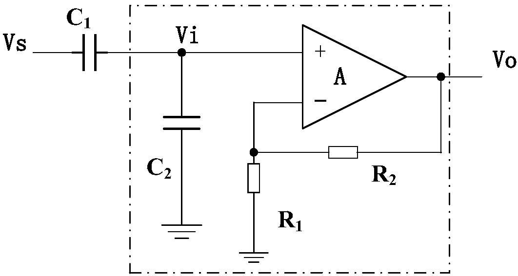
[0029] see figure 1 , including only the detection part and the basic part of the circuit. The detection part is realized by capacitive coupling, and the capacitive coupling device commonly used in the prior art can be used as the detection component to detect the measured signal Vs, and the measurement signal is generated and transmitted to the circuit input terminal Vi. The equivalent circuit diagram is as follows figure 1 The capacitance C shown 1 part. The basic part of the circuit consists of capacitor C 2 , resistor R 1 , resistor R 2 and op amp A, capacitor C 2 One end is connected to the detection signal and the non-inverting input of the operational amplifier A, and the other end is grounded; the resistor R 1 One end of the resistor is connected to the inverting input of the operational amplifier A, and the other end is grounded; the resistor R 2 One end of A is connected to the inverting input of the operational amplifier A, and the other end is connected to t...

Embodiment 2

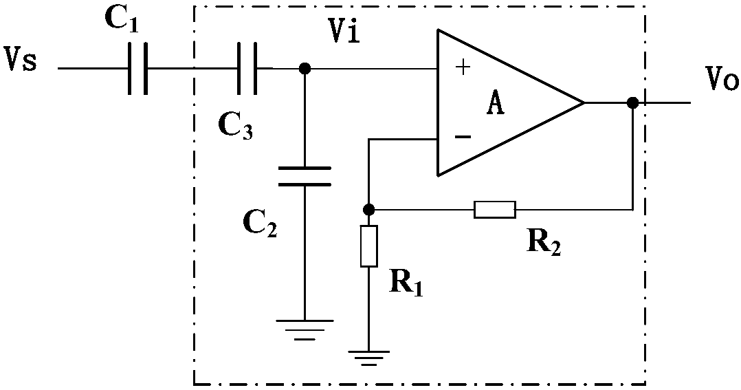
[0033] see figure 2 , including the detection part and the circuit part. The detection part remains unchanged, and the circuit part is in figure 1 circuit basis, the capacitor C 1 A capacitor C is connected in series with the connection circuit of the non-inverting input of the operational amplifier A 3 , the capacitor C 3 The output drift of the circuit can be reduced when the input coupling capacitance is large.

Embodiment 3

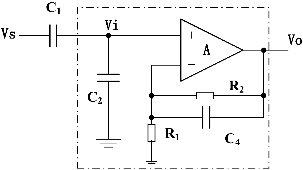
[0035] see image 3 , including the detection part and the circuit part. The detection part remains unchanged, and the circuit part is in figure 1 circuit based on the resistor R 2 Connect both ends of the capacitor C 4 , realize low-pass filtering, limit the detection signal bandwidth, and reduce the noise floor of the circuit at the same time.


PUM


Abstract

The invention discloses a non-contact sensor circuit comprising a capacitor C2, a resistor R1, a resistor R2 and an operational amplifier A. One end of the capacitor C2 is connected to a non-invertinginput terminal of the operational amplifier A and the other end of the capacitor C2 is grounded; one end of the resistor R1 is connected with an inverted input terminal of the operational amplifier Aand the other end of the resistor R1 is grounded; and one end of the resistor R2 is connected to an inverted input terminal of the operational amplifier A and the other end of the resistor R2 is connected to the output terminal of the operational amplifier A. The circuit has a simple structure; approximate direct-current signal detection on the condition of picofarad-value non-contact coupling capacitance is realized; and the gain and the bandwidth are adjustable.

Description

technical field [0001] The invention relates to a non-contact sensor circuit, in particular to a capacitive coupling type non-contact sensor circuit, which belongs to the sensing technology field of capacitive coupling mechanism. Background technique [0002] There are two types of low-frequency electrical signal detection methods: contact and non-contact. In non-contact detection, capacitive coupling is usually used for measurement. In order to achieve low frequency detection performance, a circuit with extremely high input impedance is usually required. On the other hand, due to the input leakage current in the input stage of the operational amplifier, this leakage current will continuously charge the coupling capacitor and increase the input offset voltage of the circuit, so that the output of the operational amplifier has a large DC drift, and even tends to be saturated, resulting in circuit failure. The dynamic operating range is limited and affects the operational sta...

Claims


Application Information

Patent Timeline
Patent Type & Authority Applications(China)
IPC IPC(8): G01R31/00
CPCG01R1/20G01R19/00
Inventor 张丽敏唐跃吴绒绒闫锋
Owner 南京和协集成电路科技有限公司
Why Eureka
Try Eureka