
Visualized alarm application display method, system and equipment and storage medium

A technology for displaying and invoking relationships, which is applied in the field of computer operation and maintenance, and can solve problems such as impracticability, low efficiency, and obstruction of operation and maintenance work, and achieve the effects of improving efficiency and accuracy, improving query efficiency, and solving failures

Active Publication Date: 2018-01-26
携程旅游信息技术(上海)有限公司
View PDF5 Cites 17 Cited by
  • Summary
  • Abstract
  • Description
  • Claims
  • Application Information

AI Technical Summary

Problems solved by technology

[0003] 1. The data storage of the application is usually a relational structure. When querying the application relationship, each query can only extend one call level. Due to the intricate network multi-level call relationship between applications, the traditional method needs to find the relationship of all alarm applications. It needs repeated queries many times, and the efficiency is extremely low;
[0004] 2. Due to the limitation of complexity, only the direct call relationship can be found. For the indirect call relationship, the complexity of completely finding out the relationship will rise sharply and cannot be realized;
[0005] 3. Since the call relationship of the application is a network multi-level relationship, there may be multiple paths in any two applications that can be associated. It is difficult to find the nearest path or the complete path in the traditional way.
[0006] Due to the above problems, it is difficult to clarify the call relationship between alarm applications and find the root cause of the problem, which has greatly hindered the operation and maintenance work.

Method used


Image

  • Visualized alarm application display method, system and equipment and storage medium
  • Visualized alarm application display method, system and equipment and storage medium
  • Visualized alarm application display method, system and equipment and storage medium

Examples


Embodiment Construction

[0086] Example embodiments will now be described more fully with reference to the accompanying drawings. Example embodiments may, however, be embodied in many forms and should not be construed as limited to the examples set forth herein; rather, these embodiments are provided so that this disclosure will be thorough and complete and will fully convey the concept of example embodiments to those skilled in the art. The described features, structures, or characteristics may be combined in any suitable manner in one or more embodiments.

[0087] Furthermore, the drawings are merely schematic illustrations of the present disclosure and are not necessarily drawn to scale. The same reference numerals in the drawings denote the same or similar parts, and thus repeated descriptions thereof will be omitted. Some of the block diagrams shown in the drawings are functional entities and do not necessarily correspond to physically or logically separate entities. These functional entities ...


PUM


Abstract

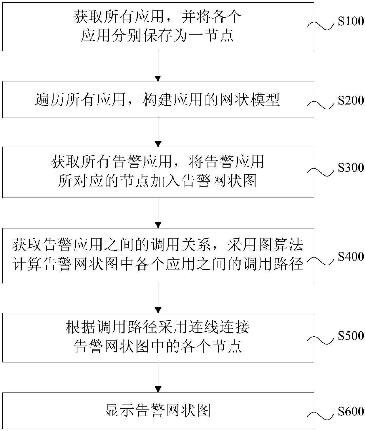
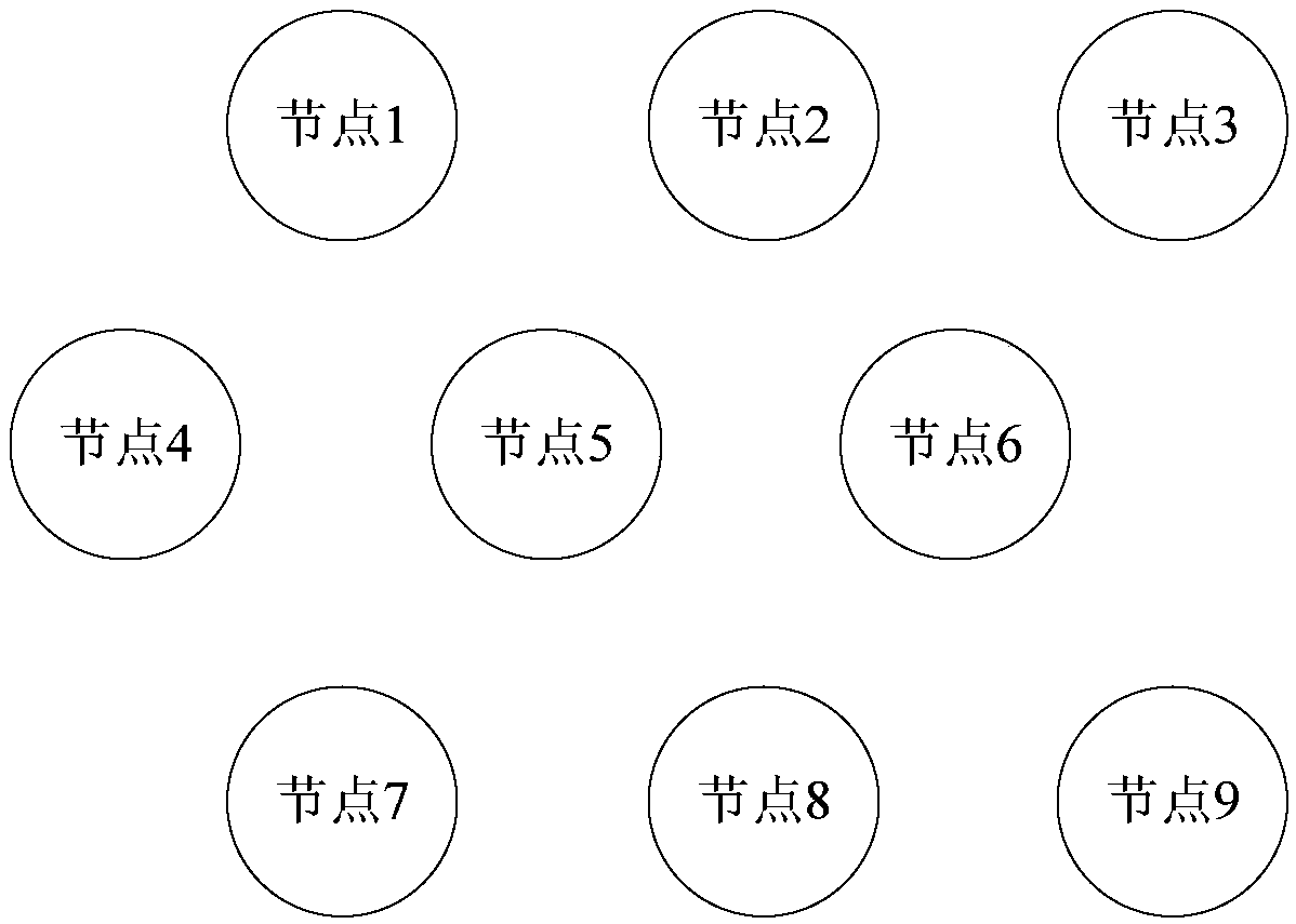
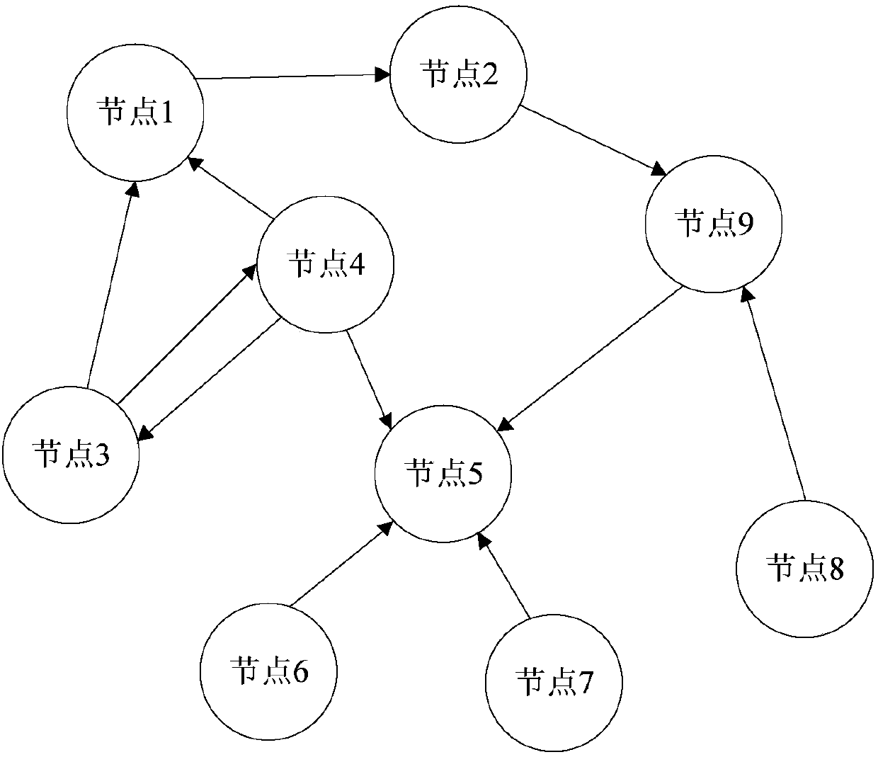
The invention provides a visualized alarm application display method, system and equipment and a storage medium. The method comprises the following steps of: obtaining information of all the applications and respectively storing each application as a node; traversing the information of all the applications and constructing a network data model of the applications, wherein the network data model ofthe applications comprises the nodes and a calling relationship among the nodes; obtaining information of all the alarm applications and adding nodes corresponding to the alarm applications into an alarm network diagram; obtaining a calling relationship among the alarm applications and calculating calling paths between adjacent applications in the alarm network diagram by adoption of a diagram algorithm; connecting the nodes in the alarm network diagram according to the calling paths by adoption of connection lines; and displaying the alarm network diagram. According to the method, data is changed from traditional relationship type storage to network structure storage, the calling relationships among the applications are directly stored, and through the diagram algorithm, the calling paths between adjacent applications can be conveniently found and displayed, so that the repeated query during the relationship search is avoided.

Description

technical field [0001] The present invention relates to the technical field of computer operation and maintenance, and in particular to a visual display method, system, device and storage medium of an alarm application that improve the query efficiency and troubleshooting efficiency of the alarm application. Background technique [0002] Most of the existing alarm application analysis is based on a single application for investigation and processing. However, once a large number of application alarms are used, there are mainly the following problems: [0003] 1. The data storage of the application is usually a relational structure. When querying the application relationship, each query can only extend one call level. Due to the intricate network multi-level call relationship between applications, the traditional method needs to find the relationship of all alarm applications. It needs repeated queries many times, and the efficiency is extremely low; [0004] 2. Due to the l...

Claims


Application Information

Patent Timeline
IPC IPC(8): G06F11/32G06F11/30
Inventor 郑嘉玮
Owner 携程旅游信息技术(上海)有限公司
Learn More