
Transformer sealing terminal and installation manufacturing technology thereof

A technology of sealed terminals and transformers, which is applied in the manufacture of inductors/transformers/magnets, transformers/inductor coils/windings/connections, electrical components, etc., to achieve economic cost savings, high installation efficiency, and good insulation performance

Inactive Publication Date: 2018-01-26
JIANGSU QIZHENG ELECTRIC POWER TECH CO LTD
View PDF4 Cites 0 Cited by
  • Summary
  • Abstract
  • Description
  • Claims
  • Application Information

AI Technical Summary

Problems solved by technology

[0005] The purpose of the present invention is to provide a transformer sealing terminal and its installation and manufacturing process in view of the current problems. The sealing terminal has a simple structure, effectively improves the installation efficiency of the transformer, has excellent anti-theft, waterproof, excellent insulation performance, and improves the operation of the transformer. The reliability provides a strong guarantee for the elimination of hidden dangers of accidents when the transformer is used in the later stage, and can meet the waterproof and sealing requirements of the low-voltage or high-voltage parts of the underground transformer

Method used


Image

  • Transformer sealing terminal and installation manufacturing technology thereof
  • Transformer sealing terminal and installation manufacturing technology thereof
  • Transformer sealing terminal and installation manufacturing technology thereof

Examples


Embodiment Construction

[0023] In order to deepen the understanding of the present invention, the present invention will be further described in detail below in conjunction with the accompanying drawings and embodiments. The following examples are only used to illustrate the technical solution of the present invention more clearly, but not to limit the protection scope of the present invention.

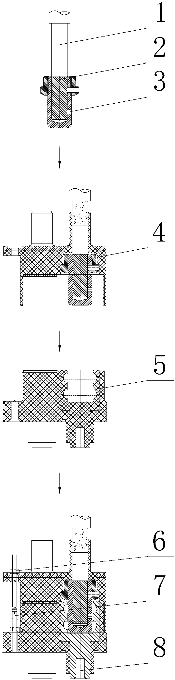
[0024] Such as figure 1 As shown, the transformer sealing terminal of the present invention includes a stress cone, a silicone sleeve, an integrated sleeve, a fixing nut, a pull rod and a conductive rod. One end of the stress cone is connected to the power cable, and the other end of the stress cone is inserted into the integrated sleeve and the integrated sleeve. Pipe connection, the silicone sleeve is set on the power cable and the stress cone, the silicone sleeve is sleeved on the integrated sleeve, the integrated sleeve is installed on the transformer body, and one end of the pull rod is screwed into the...


PUM


Abstract

The invention discloses a transformer sealing terminal. The transformer sealing terminal comprises a stress cone, a silicon rubber case, an integrated sleeve, a fixed nut, a pull rod and a conductingrod, wherein one end of the stress cone is connected with a power cable, and the other end of the stress cone is inserted into the integrated sleeve to be connected with the integrated sleeve; the silicon rubber case is arranged on the power cable and the stress cone in a sleeving manner; the silicon rubber case is connected onto the integrated sleeve in the sleeving manner; one end of the pull rod passes through the end face of the silicon rubber case to be screwed in the large end face of the integrated sleeve, and the other end of the pull rod is locked to the end face of the silicon rubbercase through the fixed nut. According to the transformer sealing terminal disclosed by the invention, seal housings and cable sealing cold-contraction tubes existing in the prior art are removed, theeconomic cost is reduced, the installation efficiency is high, the theft-proof, waterproof and insulation performances are excellent, and the service life is prolonged. Due to the fact that the brand-new sealing terminal structure and the installation manufacturing mode are adopted, the production efficiency and operational reliability are effectively improved. After sealing treatment, the waterproof performance of the transformer body terminal is strengthened, and the product operation stability is higher.

Description

technical field [0001] The invention relates to the technical field of underground transformer processing, in particular to a transformer sealing terminal and its installation and manufacturing process. Background technique [0002] China's urban construction has gone through old city demolition, building renovation and urban network transformation; it has also gone through urban green space and cable power supply, and is now entering the stage of urban beauty aimed at improving streetscape and city appearance. With the continuous deepening of urban ecological design concepts, transformers are gradually buried underground for installation. Underground transformers are designed and developed to meet the requirements of the above fields. A new type of environmentally friendly, energy-saving, and intelligent power transmission and distribution equipment, which is A fully sealed distribution transformer or combination transformer that can be installed underground (or in a pit). ...

Claims


Application Information

Patent Timeline
Patent Type & Authority Applications(China)
IPC IPC(8): H01F27/28H01F27/29H01F41/00
Inventor 刘程张福生胡绍朋
Owner JIANGSU QIZHENG ELECTRIC POWER TECH CO LTD
Learn More