Antenna

An antenna and radiating element technology, applied in antennas, resonant antennas, antenna arrays, etc., can solve the problem of low beamforming rate and achieve low intermodulation effect

Inactive Publication Date: 2018-01-26
TELEFON AB LM ERICSSON (PUBL)
View PDF15 Cites 2 Cited by
  • Summary
  • Abstract
  • Description
  • Claims
  • Application Information

AI Technical Summary

Problems solved by technology

Furthermore, the beamforming rate during the MIMO (Multiple Input Multiple Output) transmission method in antennas with interleaving is lower than in the case of antennas without interleaving

Method used


Image

  • Antenna
  • Antenna
  • Antenna

Examples


Embodiment Construction

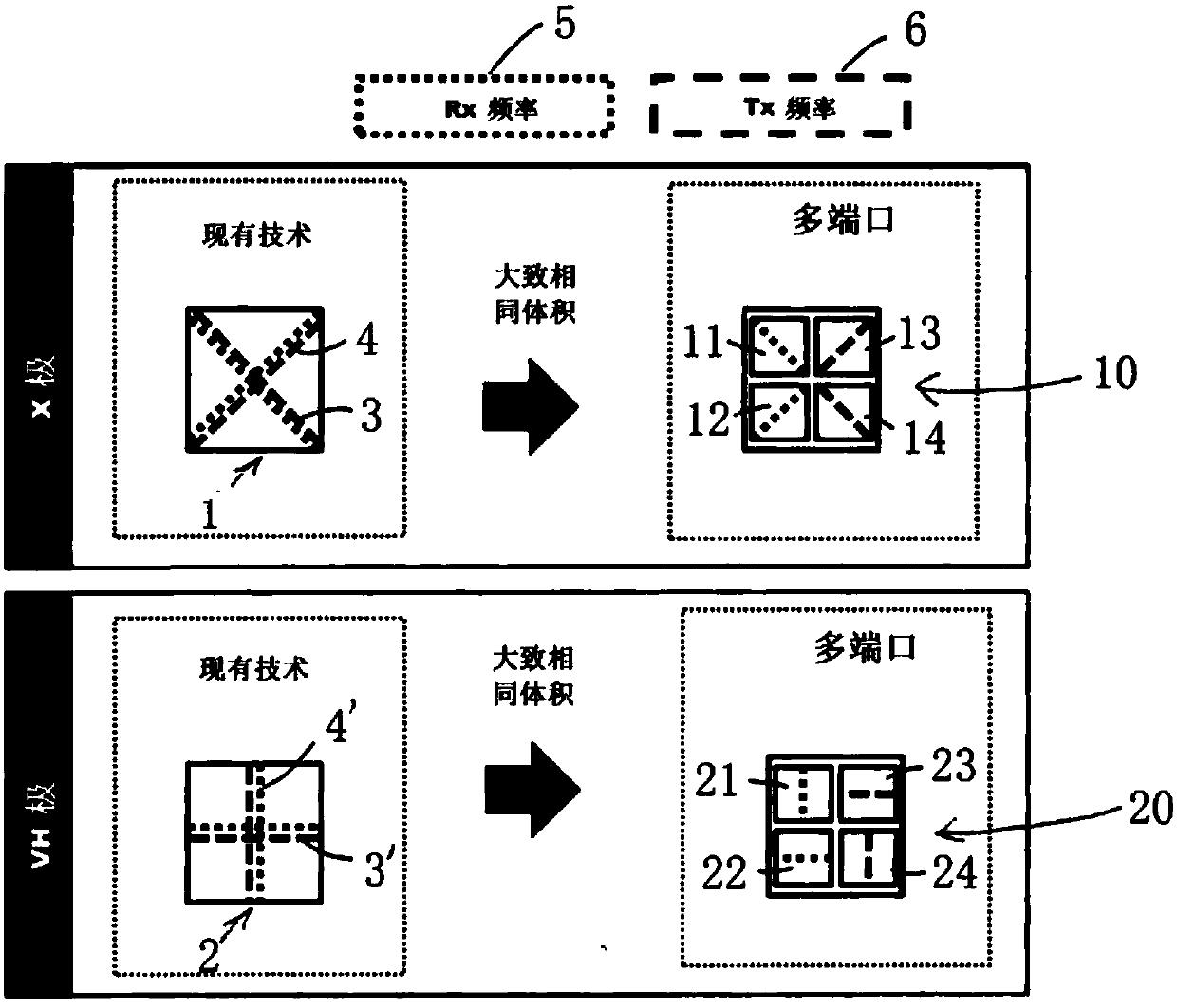
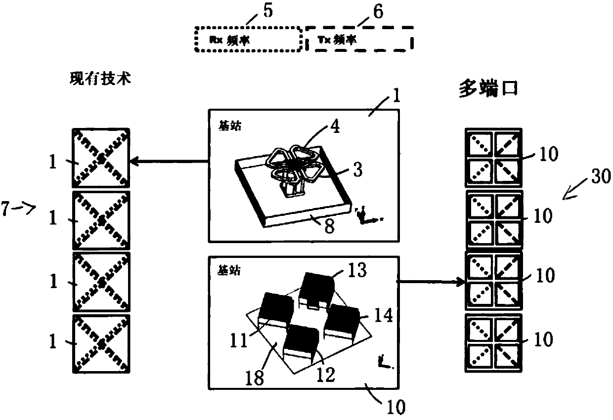
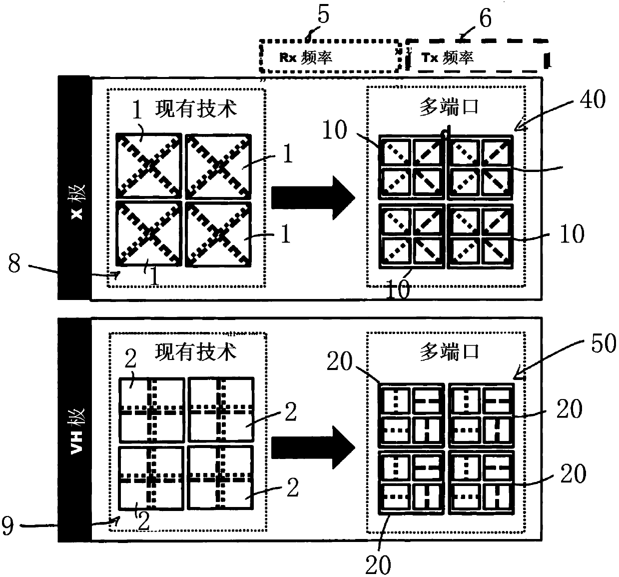
[0139] The present invention provides a multi-port antenna or a multi-port base station for multi-column antennas, which avoids the complexity and associated losses of conventional antennas in terms of the filters and duplexers used, and for the individual radiating elements The interconnect also allows flexible deployment.

[0140] figure 1 Two variants of the first embodiment of the multiport antenna or multiport base station according to the invention are shown compared to corresponding base stations according to the prior art. The use of an X-pole radiating element is shown in the upper row, and the use of a vertically polarized radiating element and a horizontally polarized radiating element is shown in the lower row. The dotted line here represents the receiving frequency 5 , and the dashed line represents the transmitting frequency 6 .

[0141] In a first embodiment of the present invention, instead of a single dual-polarized radiating element 1 and 2, multiport anten...


PUM


Abstract

The present application relates to an antenna, particularly an antenna for a mobile radio base station, having a plurality of antenna elements and having at least two transmission paths or two reception paths that are connected to two antenna elements of the antenna that are at a physical interval and have a different polarisation, wherein the antenna elements are dielectric antenna elements and/or wherein the single antenna element interval between the antenna elements is less than 0.6 lambda, wherein lambda is the wavelength of the centre frequency of the lowest resonant frequency range of the antenna elements, and to an antenna, particularly an antenna for a mobile radio base station, having at least two antenna elements that are at a physical interval and have a different polarisationand/or are operated at different frequencies, wherein the antenna elements are dielectric antenna elements having at least two separate connections for at least two different polarisations, wherein the single antenna element interval between the antenna elements is preferably less than 0.6 lambda, wherein lambda is the wavelength of the centre frequency of the lowest resonant frequency range of the antenna elements.

Description

technical field [0001] The present invention relates to an antenna, in particular to an antenna for a mobile communication base station with a plurality of radiating elements. Background technique [0002] Antennas for base stations generally have a broadband design, so that as many frequency bands as possible and as many received and transmitted signals as possible are transmitted and received with one antenna and one antenna connection. [0003] Document DE 10 2013 012 305 A1 discloses an antenna array with broadband radiating elements, wherein at least one additional radiating element emitting in a higher frequency band than the broadband radiating elements is arranged between two rows of broadband radiating elements. [0004] However, the broadband capability of the radiating elements results in large antennas and filters. [0005] Therefore, it is known from US 6211841 B1 to use different radiating elements for different frequency bands arranged in two adjacent vertica...

Claims


Application Information

Patent Timeline
Patent Type & Authority Applications(China)
IPC IPC(8): H01Q1/24H01Q9/04H01Q21/24
CPCH01Q1/246H01Q9/0485H01Q21/24H01Q19/20H01Q21/245
Inventor R·加布里埃尔A·沃尔默
Owner TELEFON AB LM ERICSSON (PUBL)
Why Eureka
Try Eureka