Transconductance stage arrangement

a transconductance stage and stage arrangement technology, applied in the direction of amplifiers with semiconductor devices only, amplifiers with semiconductor devices/discharge tubes, different amplifiers, etc., can solve the problems of reducing the gain of transconductance, introducing losses, and limited actual linearity improvement, so as to increase the input impedance, and improve the input impedance

Inactive Publication Date: 2009-12-01
HIGHBRIDGE PRINCIPAL STRATEGIES LLC AS COLLATERAL AGENT
View PDF3 Cites 3 Cited by
  • Summary
  • Abstract
  • Description
  • Claims
  • Application Information

AI Technical Summary

Benefits of technology

[0015]Particularly, for an increasing input power, the base-emitter voltage of said fourth a fourth and fifth transistors respectively is adapted to decrease rapidly, such that the corresponding DC-voltage components of the base-emitter voltages of said second and third transistors increase or do not change, hence providing a good linearity also at large RF input power.
[0018]In one implementation the base-collector (BC) junction capacitor and the load inductor (that optionally may be provided as discussed above) form a tunable series resonator. Particularly the input signal, i.e. the input voltage, has a frequency w0 and the tunable series resonator as discussed above is adapted to be tuned such that resonance will occur at twice the input frequency, i.e. at 2×ω0, such that the second harmonic of the input signal will be shorted to ground at the input, in order to further increase the linearity by reducing the third order intermodulation due to the interaction between the component of 2×ω0 and the fundamental one.

Problems solved by technology

A passive balun consisting of inductors and capacitors however requires a large chip area and normally introduces losses, which is clearly disadvantageous.
However, even if the linearity can be increased, there will be a decrease of gain in transconductance compared with an EPC and, addition thereto, the actual linearity improvement is limited due to the fundamental weakness of the emitter-coupled pair.
Therefor mixers and amplifiers based on an ECP transconductance stage are often considered insufficient as far as the fulfillment of linearity requirements are concerned for many applications.
However, even if the linearity can be improved as compared to ECP implementations, it is a problem with micromixer transconductances that the linearity deteriorates or goes down rapidly as the input RF power increases further.
This gives rise to gain compression and causes signal distortions.
Hence, there are today still no transconductances with a satisfactory linearity for several important applications, for example in wireless communication systems, but also for other applications.

Method used


Image

  • Transconductance stage arrangement
  • Transconductance stage arrangement
  • Transconductance stage arrangement

Examples


Embodiment Construction

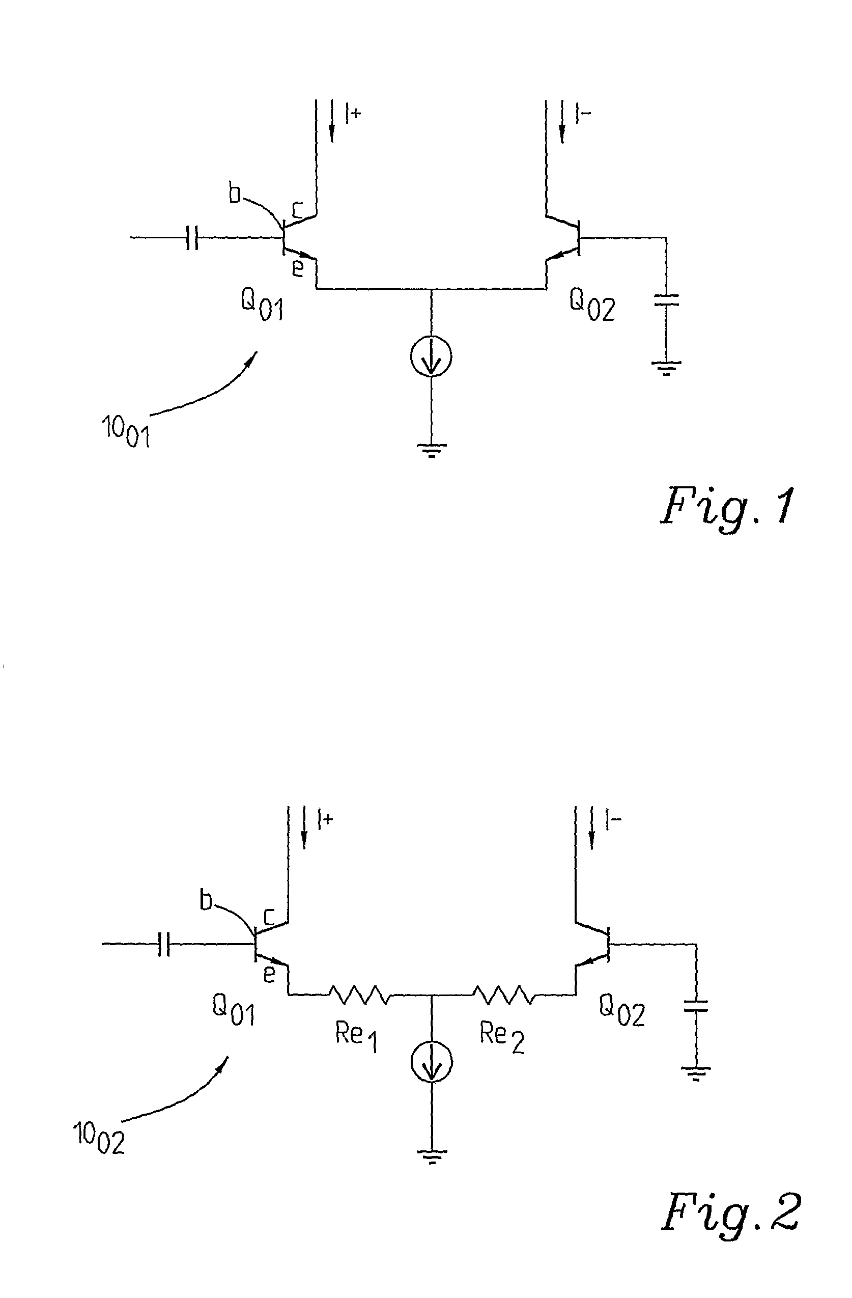
[0029]FIG. 1 very schematically illustrates an emitter-coupled pair (ECP) arrangement 1001 for an active circuit acting as a balun and a transconductance stage simultaneously with two emitter-coupled transistors Q01, Q02.

[0030]FIG. 2 schematically illustrates a similar ECP transconductance stage 1002 but with resistors Re1, Re2 connected to the respective emitters for emitter degeneration purposes, which is a known measure to increase the linearity of an arrangement as in FIG. 1.

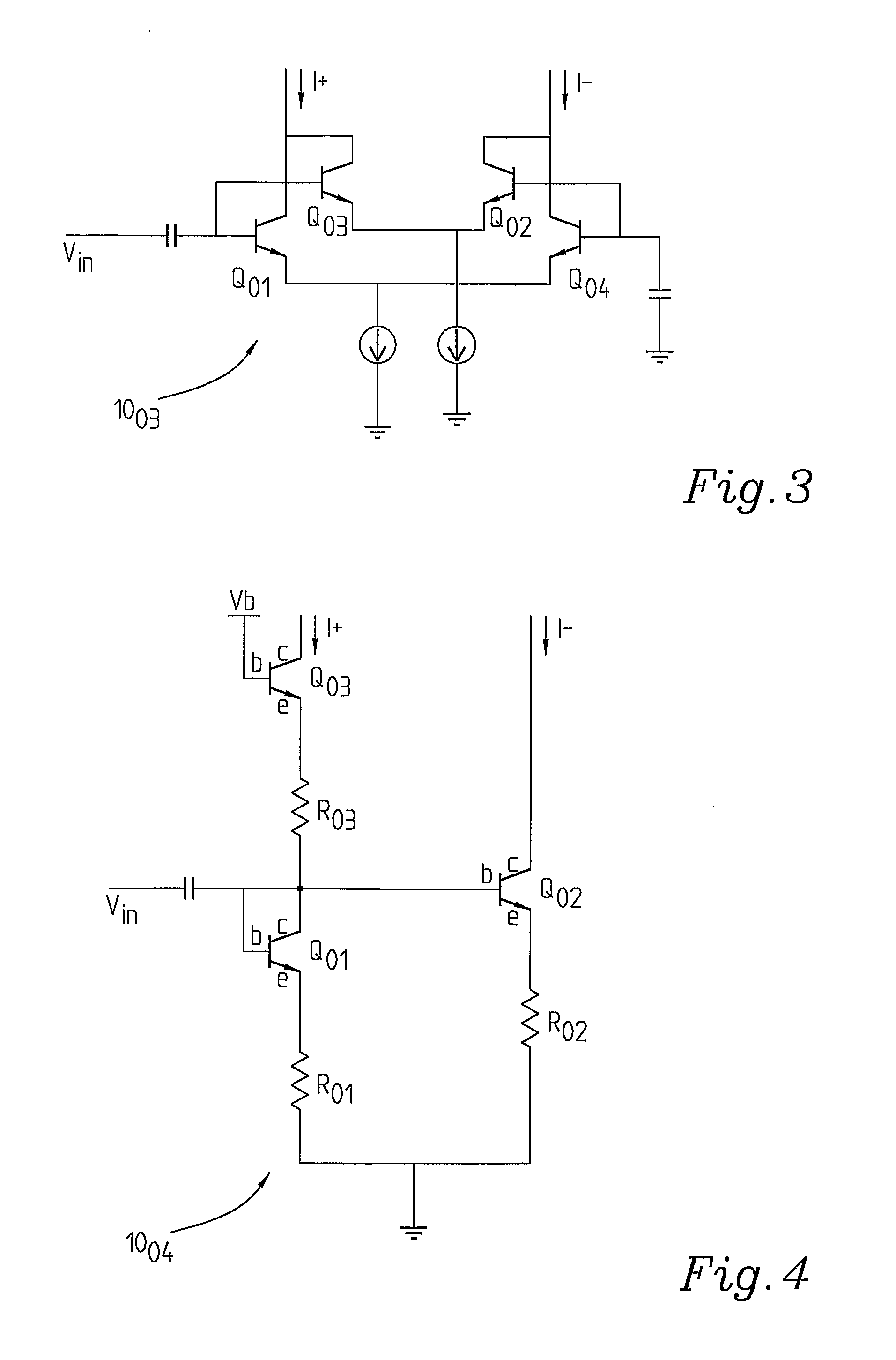
[0031]FIG. 3 shows a known multi-tan h doublet 1003. It also discloses another method for improving linearity. The sizes of Q01 and Q04 typically differ several times from the sizes of Q02 and Q03. However, all the emitter-coupled pairs are not satisfactory as far as linearity requirements are concerned for various applications, particularly due to the transconductance of the transistors decreasing considerably with an increasing input voltage applied across the bases of the transistors.

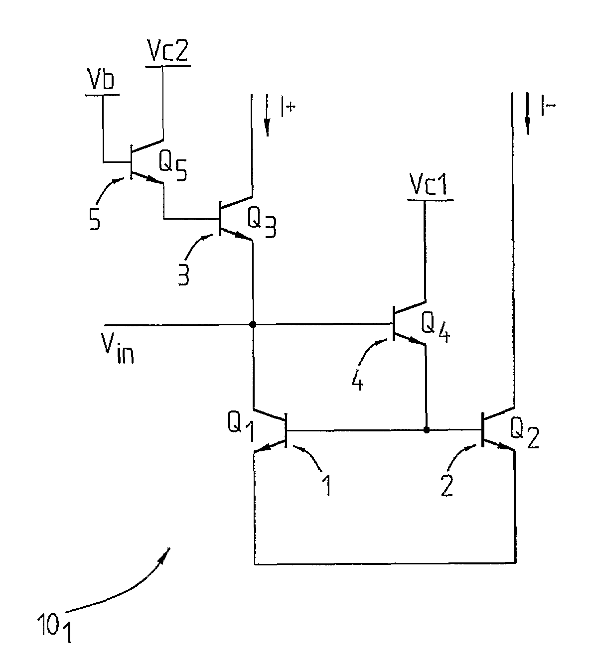
[0032]FIG. 4 schemati...


PUM


Abstract

The present invention relates to a voltage-to-current transconductance stage arrangement comprising a single-ended input, an emitter-coupled pair of transistors, comprising a first transistor and a second transistor, the emitter of a third transistor, being connected to the collector of said first transistor, and differential output. It further comprises at least one common-collector transistor comprising a fourth transistor connected to the base of said second transistor preferably or optionally also and a fifth transistor connected to the base of said third transistor. The size of said fourth, or fourth and fifth transistors considerably exceed the sizes of said second and third transistors. They are biased at ‘off-state’. An extra inductor at the collector of the transistor may be applied to further increase linearity.

Description

FIELD OF THE INVENTION[0001]The present invention relates to a voltage-to-current transconductance stage arrangement comprising a single-ended input, an emitter-coupled pair of transistors comprising a first and a second transistor, whereby the emitter of a third transistor is connected to the collector of said first transistor, and a differential output. The invention also relates to a mixer and an amplifier comprising a transconductance stage arrangement.STATE OF THE ART[0002]In many different kinds of circuits it is a requirement that the linearity is high. Examples of such arrangements or components are receivers and radio transmitters in wireless communication systems. Often the linearity of such arrangements is determined to a large extent, or mainly, by the linearity of amplifiers and mixers used in the system. Important for the linearity of such amplifiers or mixers, is the voltage-to-current transconductance stage which actually to a large extent constitutes the limiting fa...

Claims


Application Information

Patent Timeline
Patent Type & Authority Patents(United States)
IPC IPC(8): H03F3/04
CPCH03F1/3211H03F3/4508H03F2203/45291H03F2200/219H03F2203/45288H03F2200/216
Inventor BAO, MINGQUANLI, YINGGANG
Owner HIGHBRIDGE PRINCIPAL STRATEGIES LLC AS COLLATERAL AGENT
Why Eureka
Try Eureka