Movable artificial eyeball

An eyeball and ball head technology, applied in the field of machinery, can solve problems such as the inability to locate any point of the eyeball, poor system compatibility and versatility, uncontrollable eyeball movement speed, etc., to achieve easy implementation and mass production, solve rigid movement, improve The effect of simulation fidelity and fidelity

Active Publication Date: 2018-01-30
SHANGHAI JINGHONG ROBOT CO LTD
View PDF7 Cites 2 Cited by
  • Summary
  • Abstract
  • Description
  • Claims
  • Application Information

AI Technical Summary

Problems solved by technology

However, this technology belongs to a related design of the eyeball and its driving mechanism. It is not an independent eyeball and must be used as a set. The scheme is affected by a fixed electromagnetic control method, resulting in poor system compatibility and versatility; the scheme is complex in structure and involves thin Wall eyeballs, permanent magnets, miniature electromagnets, and other non-standard parts have high production costs and have not been widely used so far; the solution is to use electromagnets with specific azimuth angles to attract permanent magnets in the eyeballs, so that the eyeballs are positioned at corresponding perspective
This control method of positioning through magnets leads to uncontrollable eyeball movement speed, unable to realize the natural transition between various viewing angles, and the movements are stiff and mechanized; due to the limitation of the number of electromagnets, only a few specific eyeball angles can be realized , it is impossible to locate any point within the limit viewing angle range of the eyeball, and the simulation performance is not good

Method used


Image

  • Movable artificial eyeball
  • Movable artificial eyeball
  • Movable artificial eyeball

Examples


Embodiment 1

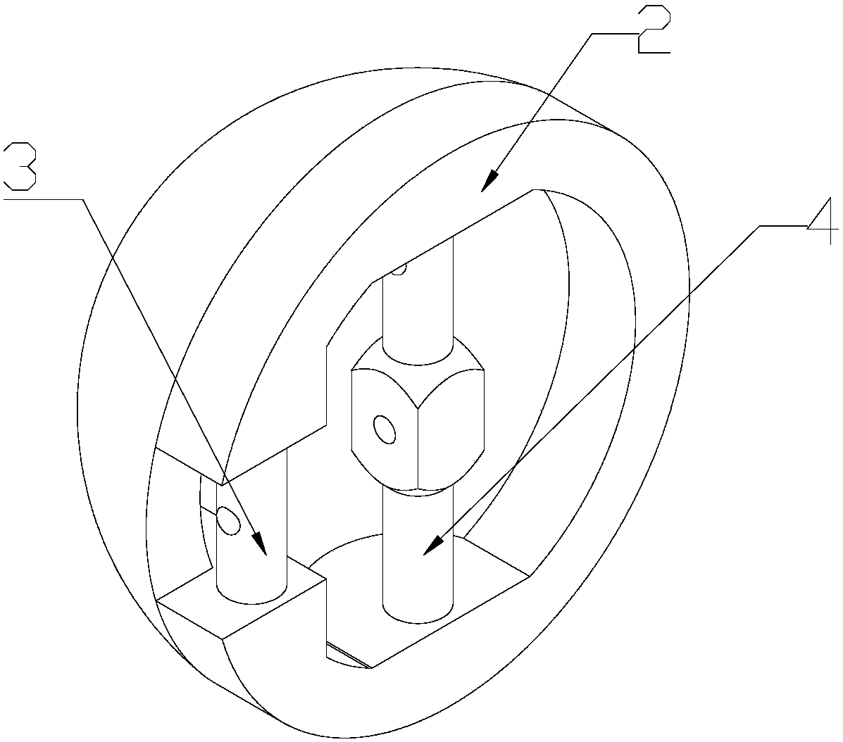
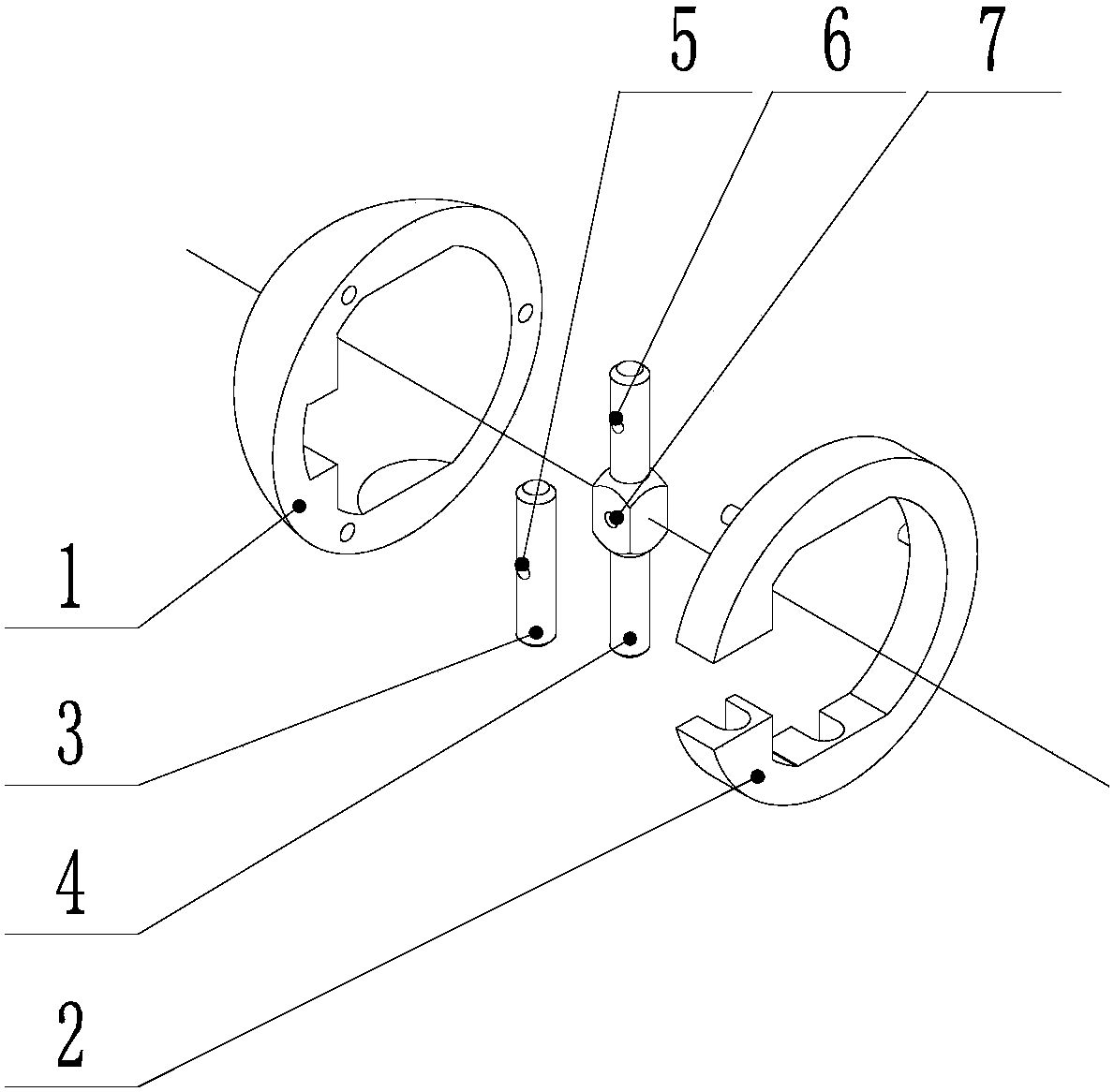
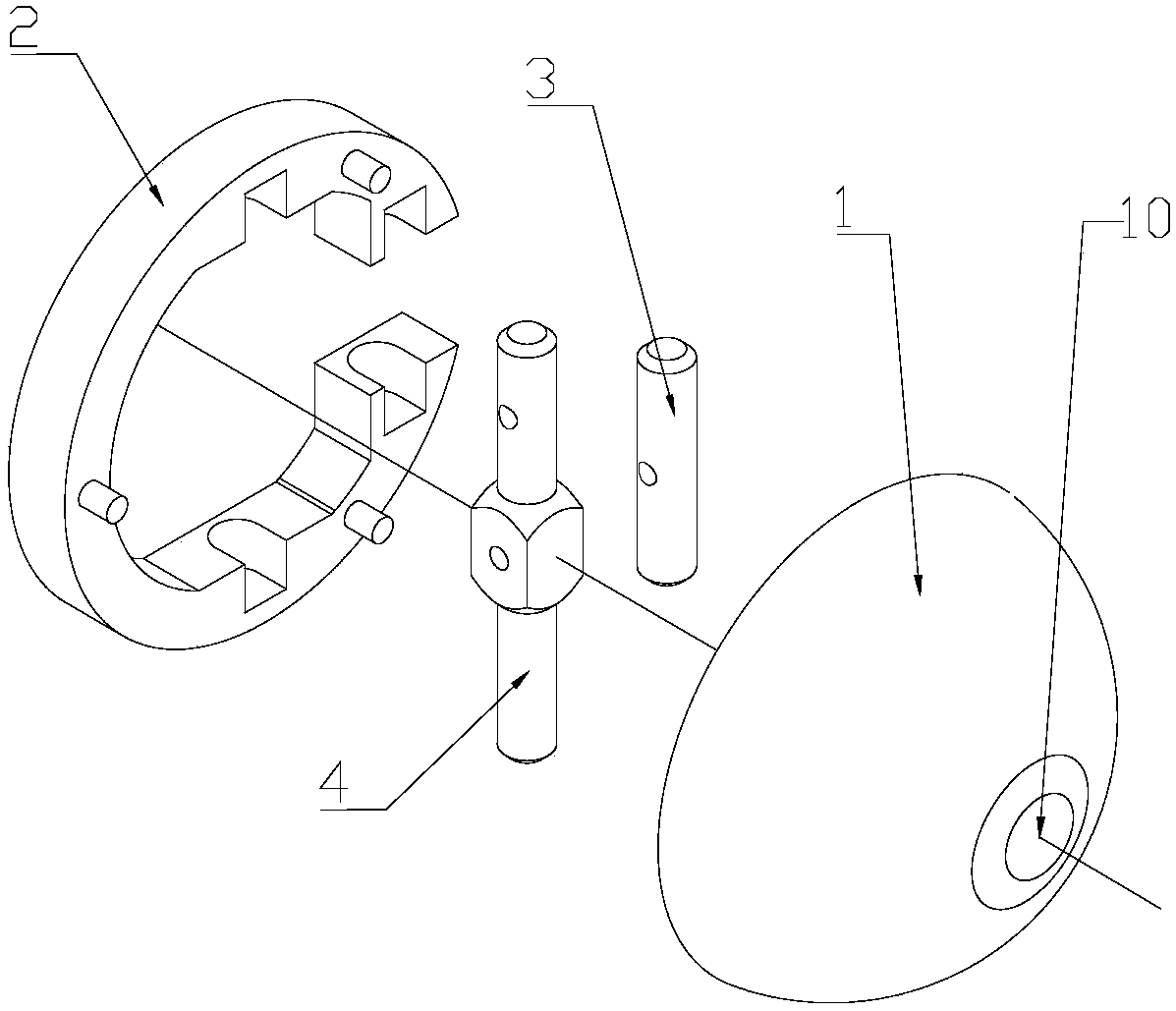
[0051] see Figure 1 ~ Figure 3 In this example, the positioning connection part on the hemisphere and the two push-pull connection parts are pivotally connected to one end of the corresponding connection device and one end of the corresponding push-pull device respectively, and the additional surface 2 is combined with the hemisphere 1 Assembly as an example.

[0052] The additional surface 2 is generally a torus with an opening; the opening is located on the side of the torus, and the bottom surface of the opening is at least below the horizontal diameter of the torus;

[0053] A main pivot 4 is vertically pivoted in the torus, the central axis of the main pivot coincides with the vertical diameter of the torus;

[0054] A secondary pivot 3 is vertically pivoted in the opening;

[0055] The main pivot 4 and the secondary pivot 3 are parallel;

[0056] The center of the main pivot 4 is provided with a central pivot hole 7 as a positioning connection part along its radial d...

Embodiment 2

[0066] see Figure 7 , This example is basically similar to Embodiment 1, except that the additional surface 2 and the hemisphere 1 are integrally formed. Shaft holes are respectively provided on the inner walls of the additional surfaces corresponding to the two ends of the main pivot and the two ends of the auxiliary pivot.

[0067] Further, for the convenience of assembly, the shaft hole corresponding to at least one end of the main pivot 4 and at least one end of the auxiliary pivot 3 is to pass through the outer wall of the hemisphere, and the hot extrusion beam is used to penetrate the shaft hole of the hemisphere. The mouth is closed, or it is sealed after being placed in the isolation film and then filled with sealing glue.

Embodiment 3

[0069] In this example, the positioning connection part on the hemisphere 1, the two push-pull connection parts and one end of the corresponding connection device and one end of the corresponding push-pull device respectively adopt ball joints as an example.

[0070] see Figure 8 ~ Figure 11 Further, the plane of the hemisphere 1 is provided with three ball sockets 15, one of which is located at the center of the plane of the hemisphere 1 to form a positioning connection, and the connecting line of the centers of the three ball sockets Form a right-angled triangle, and the other two ball sockets form a push-pull connection; the connecting device and the push-pull device respectively adopt a rod 17 with a ball head 16 at one end; a gland 18 corresponds to three ball sockets 15. After the rod hole of the gland 18 passes through the corresponding rod, the ball head 16 is pressed between the plane of the hemisphere 1 and the gland 18.

[0071] Further, the ball head 16 and the r...


PUM


Abstract

The invention relates to the technical field of machinery, and in particular relates to a movable artificial eyeball. The artificial eyeball is characterized by comprising a hemispherical body, an artificial pupil which is arranged at the apex of the hemispherical body, a locating connecting part and two push-pull connecting parts which are used for conducting pushing and pulling, wherein the push-pull connecting parts are arranged on the plane of the hemispherical body or on a same cross section, which is parallel to the plane, of the hemispherical body or on an additional surface, which is parallel to the plane, of the hemispherical body; the locating connecting part is arranged at the circle center of a plane thereof so as to movably fix the hemispherical body; one of the push-pull connecting parts is arranged on the perpendicular diameter of a plane thereof, and the other push-pull connecting part is arranged on the horizontal diameter of a plane thereof; and the two push-pull connecting parts are arranged outside the circle center. In comparison with the prior art, the artificial eyeball provided by the invention can achieve a natural and smooth conversion capacity of any viewing angles of 70 degrees within a reasonable limit viewing angle range just through two-point push-pull control, so that the simulation reduction degree and fidelity of the artificial eyeball are improved.

Description

technical field [0001] The invention relates to the field of mechanical technology, in particular to a movable artificial eyeball. Background technique [0002] With the continuous improvement of science and technology, people can use the principles of electromechanical engineering to create mechanical control systems that are more life-like than ordinary machines. Among them, there is a high-simulation robot technology that pursues high reduction and lifelike images. It is developing rapidly. According to The product attributes are different, and can be roughly divided into high-simulation mechanical animal forms, high-simulation robot real-life forms, high-simulation next-generation role game animation characters, and so on. As an indispensable and important part of the core head structure, the mechanism simulation performance of the eyeball is very important, and it plays an important role in the simulation system function. The design of the eyeball structure requires th...

Claims


Application Information

Patent Timeline
Patent Type & Authority Applications(China)
IPC IPC(8): A63H3/40A63H3/48
Inventor 周文斌王国峰
Owner SHANGHAI JINGHONG ROBOT CO LTD
Why Eureka
Try Eureka