Cable winding device

A cable and equipment technology, applied in the field of cable winding equipment, can solve the problems of cables that cannot be wound and unloaded

Inactive Publication Date: 2018-01-30
乐甜桃
View PDF13 Cites 1 Cited by
  • Summary
  • Abstract
  • Description
  • Claims
  • Application Information

AI Technical Summary

Problems solved by technology

[0006] In order to overcome the shortcomings in the prior art that a very long cable can be rewound manually and that the rewound cable cannot be unloaded, the technical problem to be solved by the present invention is to provide a cable that can be rewound without manual labor. Long cables and cable winding equipment that can unload the wound cables

Method used


Image

  • Cable winding device
  • Cable winding device
  • Cable winding device

Examples


Embodiment 1

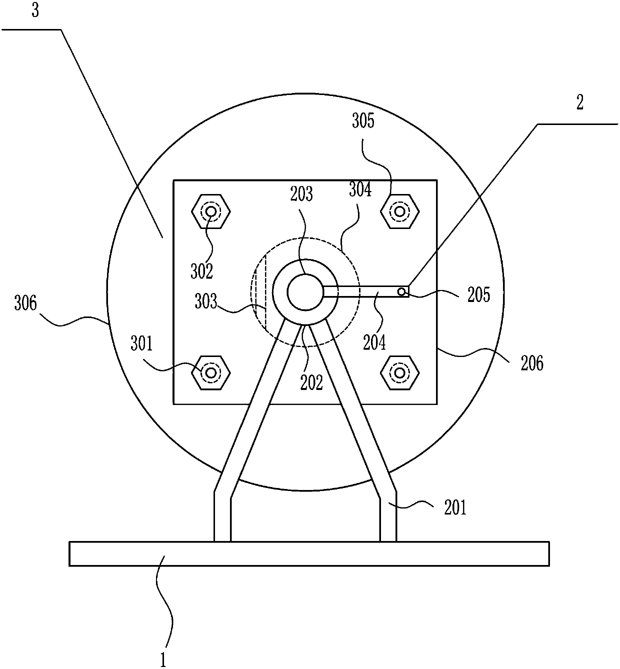
[0032]A cable winding device, such as Figure 1-5 As shown, it includes a bottom plate 1 , a rotating mechanism 2 and a winding mechanism 3 , the top of the bottom plate 1 is connected with the rotating mechanism 2 , and the rotating mechanism 2 is connected with the winding mechanism 3 .

Embodiment 2

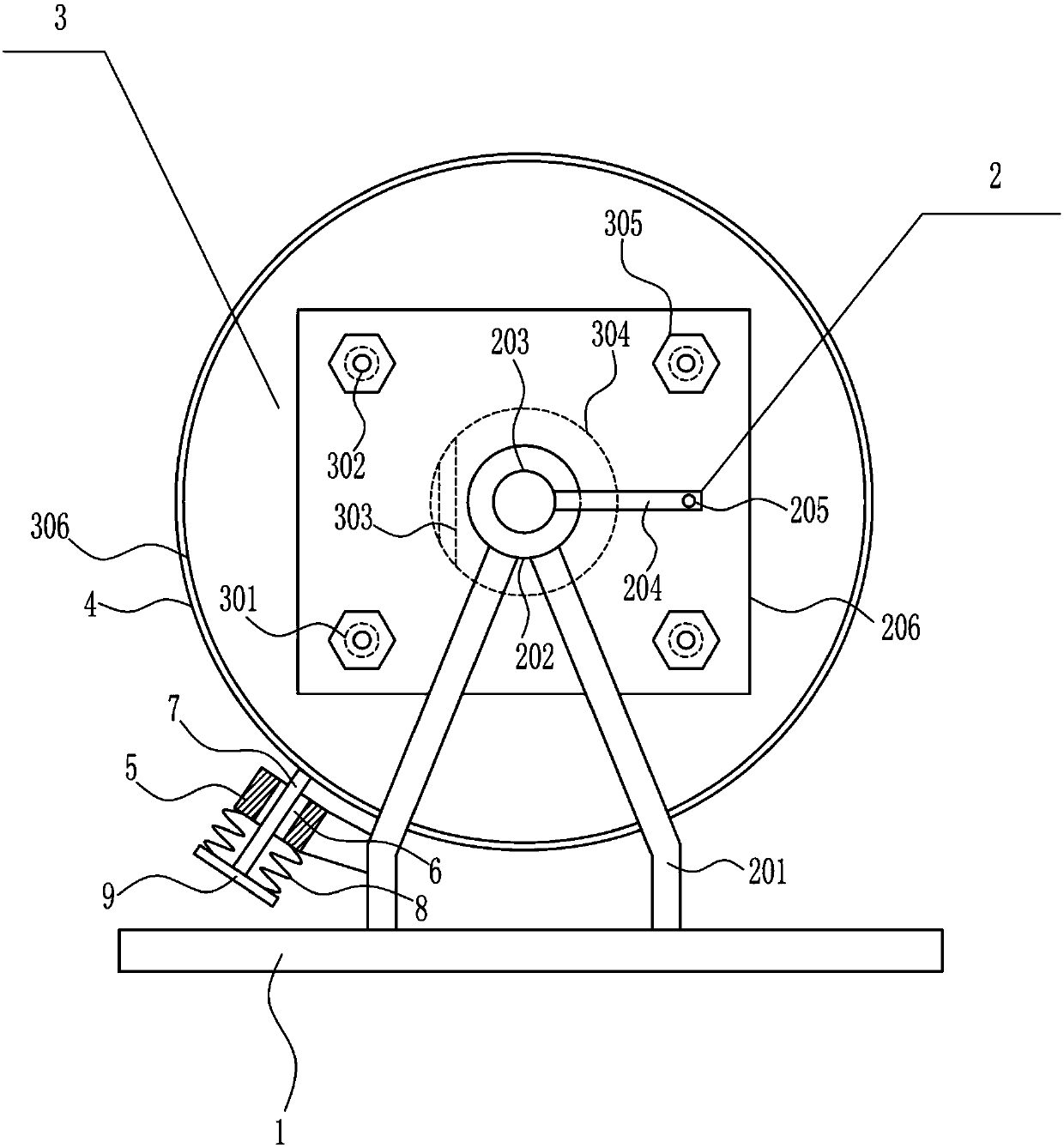
[0034] A cable winding device, such as Figure 1-5 As shown, it includes a bottom plate 1 , a rotating mechanism 2 and a winding mechanism 3 , the top of the bottom plate 1 is connected with the rotating mechanism 2 , and the rotating mechanism 2 is connected with the winding mechanism 3 .

[0035] The rotating mechanism 2 includes a bracket 201, a bearing seat 202, a first rotating rod 203, a third rotating rod 204, a handle 205 and a mounting plate 206. The front and rear sides of the top of the base plate 1 are connected with the bracket 201, and the top of the bracket 201 is connected with a bearing. Seat 202, bearing seat 202 is connected with the first rotating rod 203, the inner side of the first rotating rod 203 on the front and rear sides is connected with the mounting plate 206, the front side of the first rotating rod 203 on the front side is connected with the third rotating rod 204 , the third rotating rod 204 is located on the front side of the bearing seat 202 o...

Embodiment 3

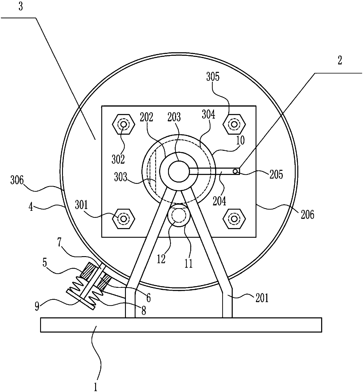
[0037] A cable winding device, such as Figure 1-5 As shown, it includes a bottom plate 1 , a rotating mechanism 2 and a winding mechanism 3 , the top of the bottom plate 1 is connected with the rotating mechanism 2 , and the rotating mechanism 2 is connected with the winding mechanism 3 .

[0038] The rotating mechanism 2 includes a bracket 201, a bearing seat 202, a first rotating rod 203, a third rotating rod 204, a handle 205 and a mounting plate 206. The front and rear sides of the top of the base plate 1 are connected with the bracket 201, and the top of the bracket 201 is connected with a bearing. Seat 202, bearing seat 202 is connected with the first rotating rod 203, the inner side of the first rotating rod 203 on the front and rear sides is connected with the mounting plate 206, the front side of the first rotating rod 203 on the front side is connected with the third rotating rod 204 , the third rotating rod 204 is located on the front side of the bearing seat 202 o...


PUM


Abstract

The invention relates to a winding device, in particular to a cable winding device, and aims to provide a cable winding device which can wind long cables without labor and can unload wound cables. Thecable winding device comprises a bottom plate and the like, a rotating mechanism is connected at the top of the bottom plate, and a winding mechanism is connected on the rotating mechanism. The cablewinding device has the advantages that the device can wind the long cables without the labor and unload the wound cables, a lifting rod vertically moves, so that the lifting rod can cling to an annular rubber ring, a rotating cylinder cannot easily rotate, the wound cables cannot reversely rotate and fall off, a first annular baffle plate and a mounting plate are dissembled and assembled, and thecables can be conveniently wound by users.

Description

technical field [0001] The invention relates to a winding device, in particular to a cable winding device. Background technique [0002] The cable supports high-definition video transmission, accurate data transmission and KVM (keyboard, display and mouse) technology, and is the best solution for professional video and data applications, while providing excellent low-skew performance for component video applications , Comply with and apply to TIA or EIA standard. [0003] Cables are one of the most common data transmission lines in today's society, and there are many equipment for winding cables, but each has its own advantages and disadvantages, and many of the existing cable winding equipment have It is impossible to stop winding the cable at any time, and there are many devices that use manual rotation to wind the cable. In this way, when facing a relatively long cable, it is more time-consuming to use labor. [0004] Therefore, it is urgent to develop a kind of cable w...

Claims


Application Information

Patent Timeline
Patent Type & Authority Applications(China)
IPC IPC(8): B65H54/40B65H54/28B65H67/04
Inventor 乐甜桃秦子淋贺琛
Owner 乐甜桃
Why Eureka
Try Eureka