Portable multifunctional hydraulic oil testing and maintenance device

A hydraulic oil and portable technology, applied in mechanical equipment, fluid pressure actuation system testing, fluid pressure actuation devices, etc., can solve problems such as poor application of hydraulic engineering, complex structure of detectors, and low level of functional integration , to achieve the effect of reducing labor costs, convenient operation, and reducing heat

Active Publication Date: 2018-01-30
中化学环境发展(北京)有限公司
View PDF9 Cites 2 Cited by
  • Summary
  • Abstract
  • Description
  • Claims
  • Application Information

AI Technical Summary

Problems solved by technology

The off-line hydraulic oil particle size detector needs to sample the contaminated hydraulic oil and is difficult to operate. This kind of detector has a complex structure, low function integration and very expensive price; There are few applications in industrial industries with harsh environments and extensive management, but it is these industrial industries with harsh environments that have an urgent need for quick, simple and low-cost detection and purification of hydraulic oil
The online particle size detector is small in size, but its integration is extremely low. It needs to be designed and installed separately before it can be used normally in the hydraulic system. Moreover, its detection accuracy is very low, and in many cases it cannot meet the detection requirements. Therefore, the market share low rate
[0005] When the hydraulic system leaks, there is no product on the market that can accurately detect the leak location and amount of the hydraulic system, and there is no product that can detect the leakage of the hydraulic oil, the degree of pollution, and the cleaning function of the hydraulic oil. Perfectly integrated, easy to carry and powerful, it cannot be well applied in the front line of hydraulic engineering

Method used


Image

  • Portable multifunctional hydraulic oil testing and maintenance device
  • Portable multifunctional hydraulic oil testing and maintenance device
  • Portable multifunctional hydraulic oil testing and maintenance device

Examples


Embodiment Construction

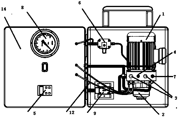
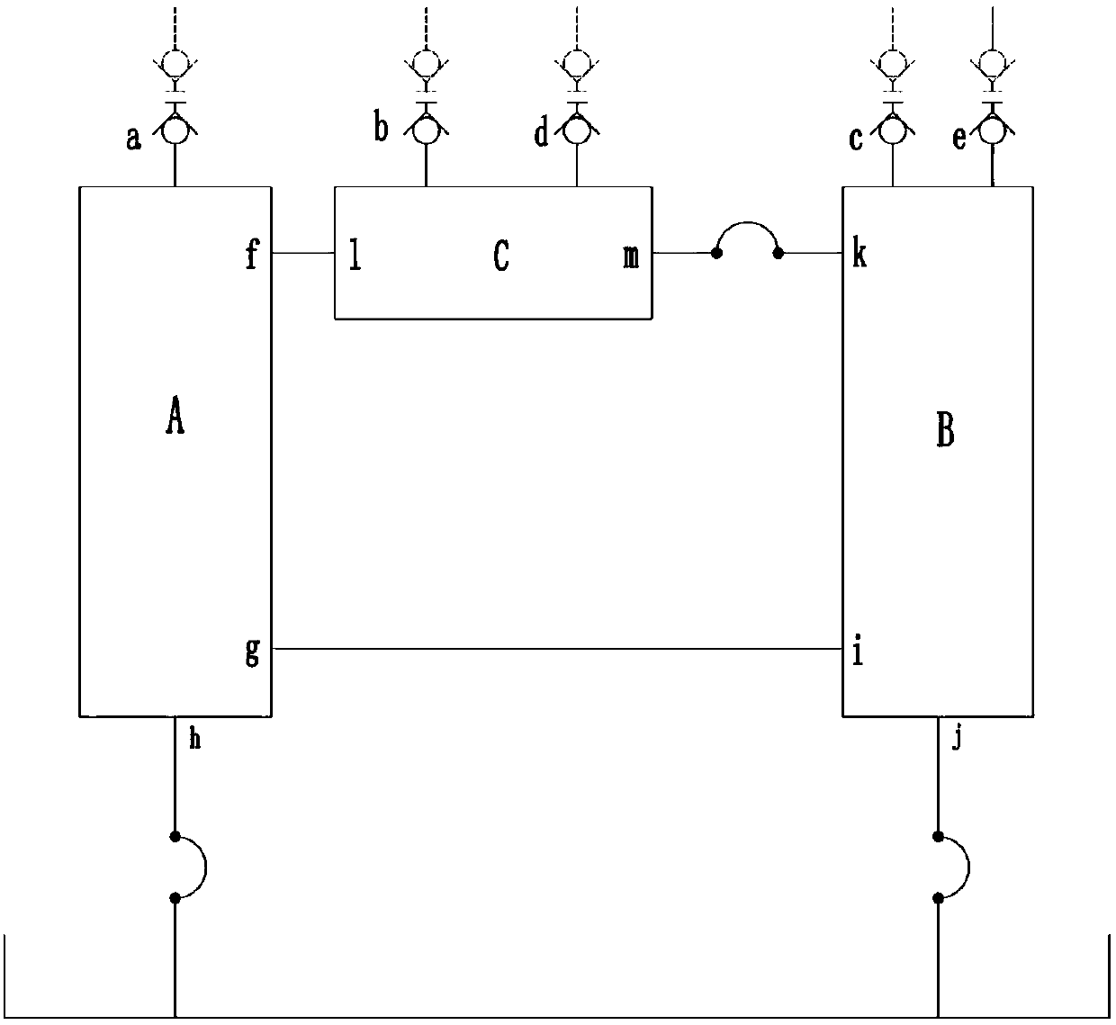
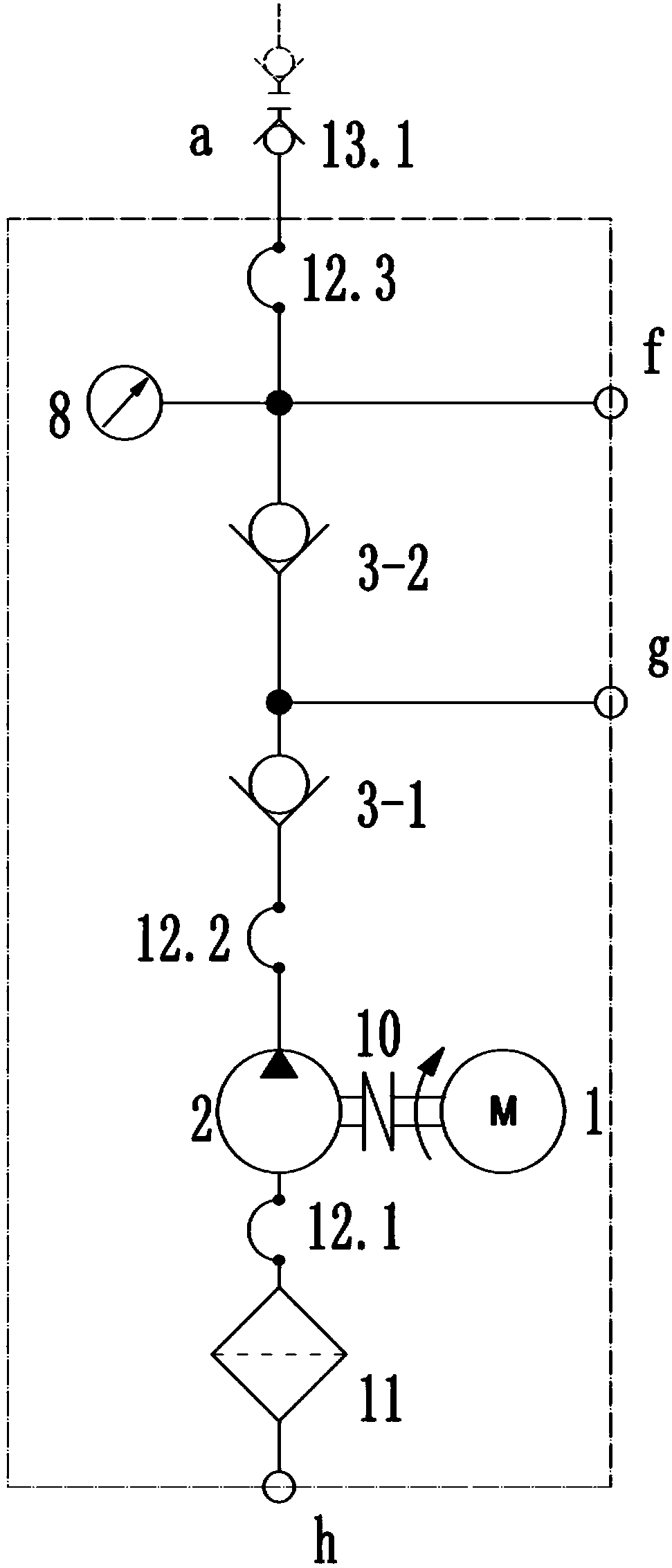
[0031] exist figure 1 In the schematic diagram of an embodiment of a portable multifunctional hydraulic oil detection and maintenance device shown, the present invention mainly includes: a power component A, a medium pollution state detection and medium cleaning component B and a leakage detection component C. Among them, power component A such as figure 2 As shown, the motor 1 is connected to the hydraulic pump 2 through the coupling 10, the oil suction port of the hydraulic pump 2 is connected to the outlet of the oil suction filter 11 through the hydraulic hose 12.1, and the inlet of the oil suction filter 11 can be connected to the system to be tested through the hydraulic hose The hydraulic oil tank, the oil pressure port of the hydraulic pump 2 is connected to the oil inlet port of the first one-way valve 3-1 through the hydraulic hose 12.2, and the oil outlet port of the one-way valve 3-1 is connected to the oil port of the second one-way valve 3-2. The oil inlet is c...


PUM


Abstract

The invention provides a portable multifunctional hydraulic oil testing and maintenance device, which comprises a power assembly A, a medium pollution status detection and medium cleaning assembly B,and a leakage detection assembly C. The power assembly A comprises a motor, a hydraulic pump, a check valve, a pressure visualization measuring device, a coupling, an oil suction filter, a hydraulic hose, and a hydraulic quick-change connector. The medium pollution status detection and medium cleaning assembly B comprises a flow control device, a pollution degree detection device, a hydraulic oilcleaning device, a hydraulic hose, and a hydraulic quick-change connector; the leakage detection assembly C comprises a flow measurement device, a pressure maintenance device, a hydraulic hose, and ahydraulic quick-change connector. The device combines the detection of hydraulic oil pollution degree, the detection of hydraulic oil leaks, and the cleaning of hydraulic oil to easily detect and maintain the hydraulic oil in one machine; at the same time, the device has a portable design and is small in size, thus it is convenient to move and able to move freely on open spaces, and even can be carried by maintenance personnel on business trips.

Description

technical field [0001] The invention relates to a hydraulic oil detection and maintenance equipment Background technique [0002] The main function of hydraulic oil in the hydraulic system is to transmit power, and at the same time lubricate and protect the moving parts in the hydraulic system. The equipped hydraulic control system is very precise, and some hydraulic control is realized by throttling small holes, the gap is small, and the cleanliness of the hydraulic oil is highly required. 70% of hydraulic system failures are caused by hydraulic system pollution, and hydraulic system failures caused by solid particle pollutants account for 60% to 70% of the total pollution failures. The failure of the hydraulic system will lead to economic losses or even serious accidents, so how to quickly detect and control the hydraulic oil particle pollution in the hydraulic system is an urgent problem to be solved for equipment maintenance and repair. [0003] Leakage of hydraulic oi...

Claims


Application Information

Patent Timeline
Patent Type & Authority Applications(China)
IPC IPC(8): F15B19/00F15B21/04
Inventor 郭锐张弛王萍
Owner 中化学环境发展(北京)有限公司
Why Eureka
Try Eureka