
Test method and system for micro grid energy management system

An energy management system and test method technology, applied in the field of real-time simulation test of power system, can solve the problems of single test, high cost, poor real-time performance, etc., and achieve the effect of strong scalability

Pending Publication Date: 2018-01-30
SHANGHAI ELECTRIC DISTRIBUTED ENERGY TECH CO LTD
View PDF6 Cites 11 Cited by
  • Summary
  • Abstract
  • Description
  • Claims
  • Application Information

AI Technical Summary

Problems solved by technology

[0008] In view of the above-mentioned defects of the prior art, the technical problem to be solved by the present invention is to provide a testing method and system for a micro-grid energy management system to solve the problem that the test of the micro-grid energy management system needs to be equipped with a variety of equipment, which is difficult to build, high in cost, and Single test and poor real-time performance

Method used


Image

  • Test method and system for micro grid energy management system
  • Test method and system for micro grid energy management system
  • Test method and system for micro grid energy management system

Examples


Embodiment 1

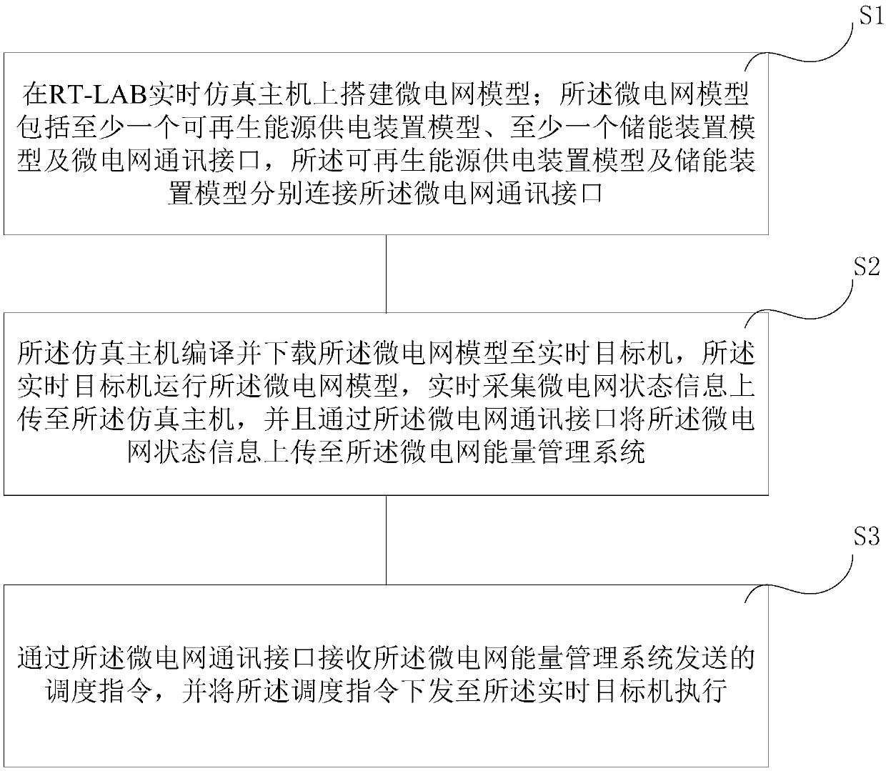
[0046] figure 1 It is a schematic diagram of a test method for a microgrid energy management system according to Embodiment 1 of the present invention, as shown in figure 1 As shown, the testing method for the microgrid energy management system of this embodiment includes the following steps:

[0047] Step S1: Build a microgrid model on the RT-LAB real-time simulation host; the microgrid model includes at least one model of a renewable energy power supply device, at least one model of an energy storage device, and a communication interface for a microgrid, wherein the model of a renewable energy power supply device and The energy storage device models are respectively connected to the microgrid communication interface; for example, the renewable energy power supply device models are green energy power supply devices such as fan models and photovoltaic models; the energy storage device models include energy storage converters (Power Control System—PCS) and The energy storage s...

Embodiment 2

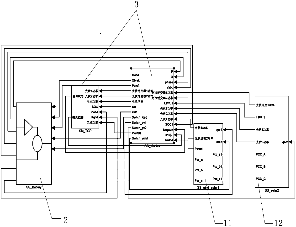
[0053] see Figure 4 As shown, it is a wind-solar storage and off-grid microgrid system, in which the renewable energy power supply device includes a photovoltaic device 1, a photovoltaic device 2 and a fan device, as well as an energy storage device and a load device integrated into the grid.

[0054] In this embodiment, the above-mentioned microgrid model is built on the RT_LAB real-time simulation host, this step is similar to step 1 in Embodiment 1, and will not be repeated here. And, each device model in the microgrid model is connected to the inverter model, such as Figure 4 It includes photovoltaic inverter 1, photovoltaic inverter 2, wind turbine inverter and energy storage inverter. These inverters can collect the microgrid status information in real time, and perform Processing and calculation of real-time power, taking photovoltaic inverter 1 as an example, it can collect the state information of its corresponding photovoltaic device 1, including real-time collect...


PUM


Abstract

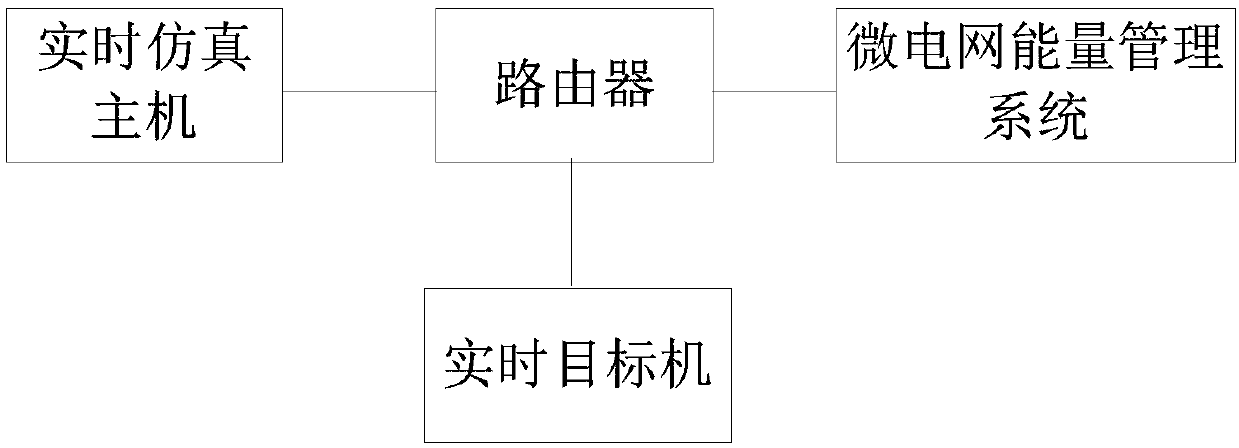
The invention provides a test method and system for a micro grid energy management system. The test method comprises the steps that a micro grid model is built on an RT-LAB real-time simulation host;the micro grid model comprises at least one renewable energy power supply device model, at least one energy storage device model and a micro grid communication interface; the renewable energy power supply device model and the energy storage device model are connected with the micro grid communication interface respectively; the simulation host compiles and downloads the micro grid model to a real-time target machine; the real-time target machine runs the micro grid model, acquires the status information of a micro grid in real time, and uploads the information to the simulation host; the status information of the micro grid is uploaded to the micro grid energy management system through the micro grid communication interface; a dispatch instruction sent by the micro grid energy management system is received through the micro grid communication interface; and the dispatch instruction is issued to the real-time target machine for execution. The test method and system have the advantages of low cost, convenient realization, comprehensive problem testing and good real-time performance.

Description

technical field [0001] The invention relates to the field of real-time simulation testing of power systems, in particular to a testing method and system for a microgrid energy management system. Background technique [0002] With the depletion of petrochemical energy and the rapid development of new energy power generation, green energy represented by distributed microgrids has gradually attracted people's attention. Compared with traditional fossil fuel power generation technologies, the power generated by distributed microgrids is often random and cannot Directly put into use, the micro-grid energy management system is the key technology to realize the distributed micro-grid for people to use. Equipped with the micro-grid energy management system, the distributed micro-grid becomes intelligent, efficient, economical and environmentally friendly; As the core of the flexible operation of the microgrid system, it is very important to test the microgrid energy management algor...

Claims


Application Information

Patent Timeline
Patent Type & Authority Applications(China)
IPC IPC(8): G01R31/00G06F17/50
Inventor 许泽阳夏耀杰吕楠刘伟陈锋
Owner SHANGHAI ELECTRIC DISTRIBUTED ENERGY TECH CO LTD
Learn More