Cone-shaped beam scanning CTS antenna

A technology of beam scanning and antenna, which is applied in the field of microwave and millimeter wave antennas, can solve the problems of low gain, narrow bandwidth, large size of beam scanning CTS antenna, etc., to improve antenna gain and radiation efficiency, widen antenna bandwidth, and good beam stability Effect

Inactive Publication Date: 2018-01-30
NANJING UNIV OF SCI & TECH
View PDF6 Cites 10 Cited by
  • Summary
  • Abstract
  • Description
  • Claims
  • Application Information

AI Technical Summary

Problems solved by technology

[0005] In short, the problems existing in the existing technology are: the beam scanning CTS antenna has a large size, narrow bandwidth, and low gain, and cannot meet the requirements of radar tracking technologies such as 5G communication, precision measurement, fire control, reconnaissance and calibration, space detection, and missile guidance. need

Method used


Image

  • Cone-shaped beam scanning CTS antenna
  • Cone-shaped beam scanning CTS antenna
  • Cone-shaped beam scanning CTS antenna

Examples


Embodiment Construction

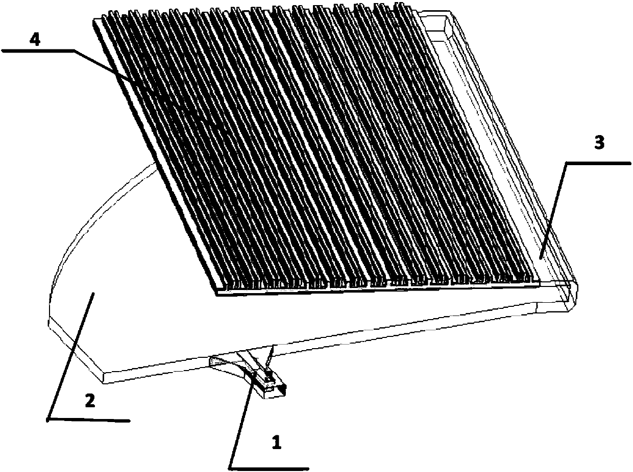
[0029] Such as figure 1 Shown, a kind of cone-beam scanning CTS antenna of the present invention,

[0030] Including 1 H-plane ridged waveguide horn, 1 Pillbox offset parabolic box, U-shaped slab waveguide and slab waveguide CTS array;

[0031] The H-surface ridged waveguide horn is placed on the Pillbox offset parabolic box side wall opposite to the Pillbox offset parabolic box reflective surface, and its phase center is aligned with a certain fixed point on the Pillbox offset parabolic box reflective surface;

[0032] The flat plate waveguide CTS array is placed above the Pillbox offset parabolic box, one side of which is connected to one end of the U-shaped flat plate elbow, and one end of the U-shaped flat plate elbow is connected to the diameter of the Pillbox offset parabolic box;

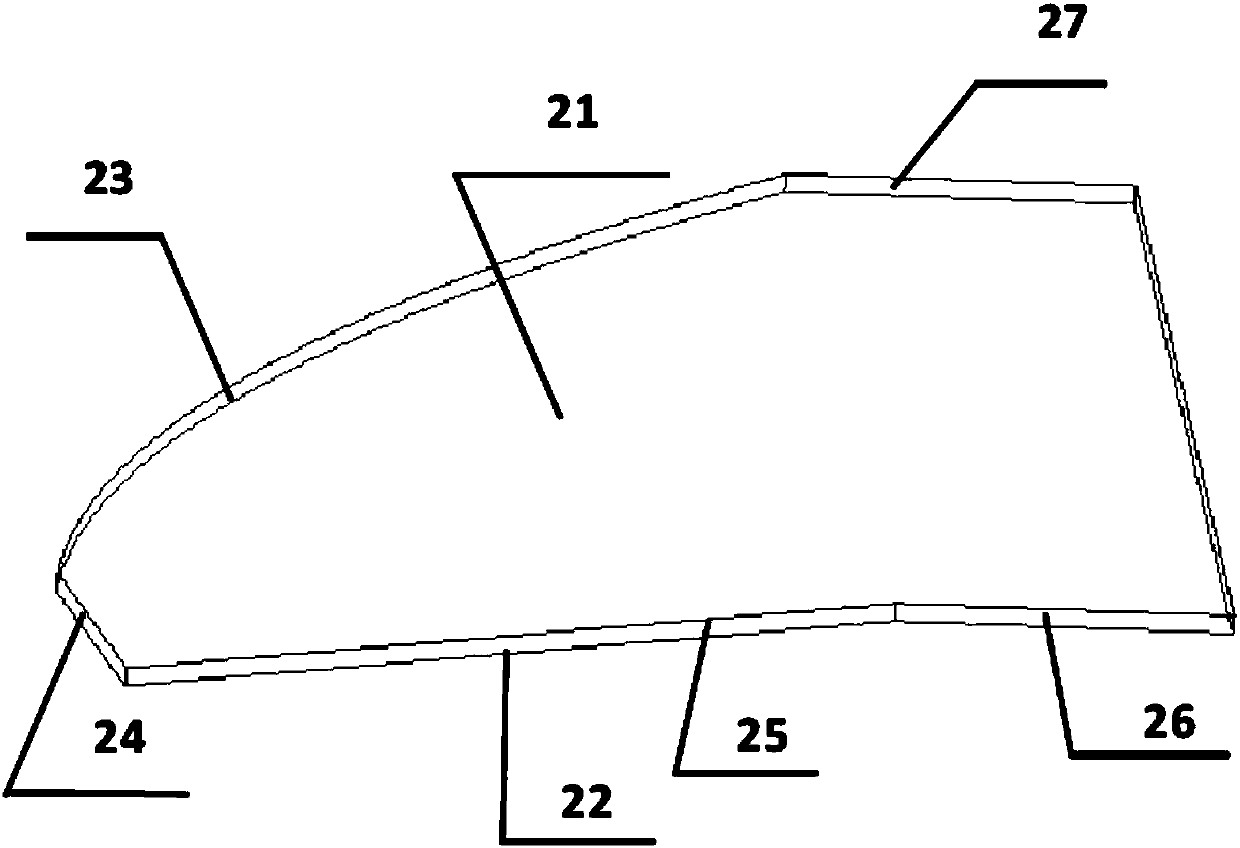
[0033] Such as figure 2 As shown, the Pillbox offset parabolic box includes a top plate, a bottom plate, a parabolic curved surface placed in parallel, a left side wall, a front side wall,...


PUM


Abstract

The invention discloses a cone-shaped beam scanning CTS antenna which comprises an H-surface ridge-adding horn (1), a Pillbox offset parabolic box (2), a U-shaped flat plate elbow (3) and a flat waveguide CTS array (4), wherein the flat waveguide CTS array is arranged above a Pillbox offset parabolic box (2); one side of flat waveguide CTS array (4) is connected with one end of the U-shaped flat plate elbow (3), of which the other end is connected with the caliber port of Pillbox offset parabolic box (2), the H-surface ridge-adding horn (1) is placed in the side wall of the Pillbox offset parabolic box (2) opposite to the reflecting surface of the Pillbox offset parabolic box (2), and the phase center aligns with a certain fixed point on the reflecting surface of the Pillbox offset parabolic box (2). According to the cone-shaped beam scanning CTS antenna, the frequency band is wide, the gain is high, and the beam is stable.

Description

technical field [0001] The invention relates to the field of microwave and millimeter wave antennas, in particular to a cone beam scanning CTS antenna with wide frequency band, high gain and stable beam. technical background [0002] The CTS (Continuous Transverse Stub) antenna reduces reflection by creating a transverse slot on the planar waveguide and placing metal baffles on the two long sides of the slot. Due to the simple feeding structure of the CTS antenna, insensitivity to processing accuracy and dielectric materials, and high radiation efficiency, it has become an important research direction for high-gain antennas. [0003] Chinese invention patent application "parabolic box fed multi-beam CTS flat panel antenna" (application number: 2017103329527, application date: 2017.05.16) discloses a parabolic box fed multi-beam CTS flat panel antenna, including a planar waveguide CTS array, two Parabolic reflector feed box and 6 waveguide horns. In this device, two identic...

Claims


Application Information

Patent Timeline
Patent Type & Authority Applications(China)
IPC IPC(8): H01Q1/12H01Q1/50H01Q13/02H01Q19/13
Inventor 齐世山印倩吴文刘亮亮王轶豪
Owner NANJING UNIV OF SCI & TECH
Why Eureka
Try Eureka