Satellite navigation antenna

A satellite navigation antenna and antenna technology, applied in the field of satellite navigation antennas, can solve the problems of heavy weight, high cost, and low precision of satellite navigation antennas

Pending Publication Date: 2018-01-30
XIAN UNISTRONG NAVIGATION TECH CO LTD
View PDF0 Cites 2 Cited by
  • Summary
  • Abstract
  • Description
  • Claims
  • Application Information

AI Technical Summary

Problems solved by technology

[0005] In view of this, the object of the present invention is to provide a satellite navigation antenna to sol

Method used


Image

  • Satellite navigation antenna
  • Satellite navigation antenna
  • Satellite navigation antenna

Examples


Embodiment Construction

[0038] In order to make the purpose, technical solutions and advantages of the embodiments of the present invention clearer, the technical solutions in the embodiments of the present invention will be clearly and completely described below in conjunction with the drawings in the embodiments of the present invention. Obviously, the described embodiments It is a part of embodiments of the present invention, but not all embodiments. Based on the embodiments of the present invention, all other embodiments obtained by persons of ordinary skill in the art without making creative efforts belong to the protection scope of the present invention.

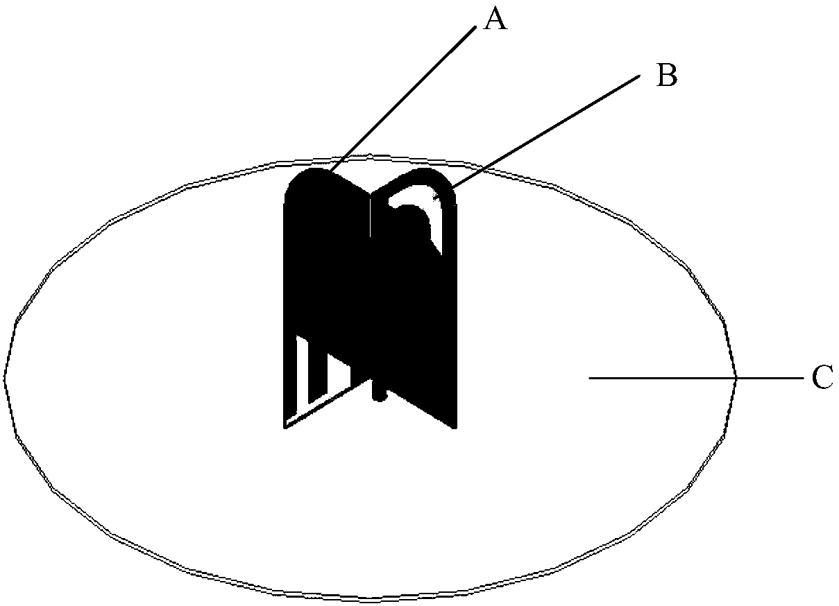
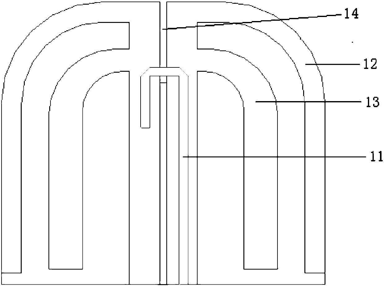
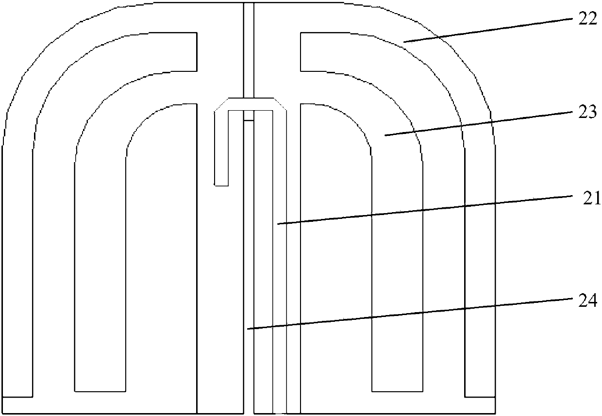
[0039] The following will combine Figure 1-Figure 4 The structure of the satellite navigation antenna provided by the embodiment of the present application is introduced in detail.

[0040] figure 1 It shows a schematic structural diagram of a satellite navigation antenna according to an embodiment of the present application, figure 2 A ...


PUM

PropertyMeasurementUnit
Horizontal lengthaaaaaaaaaa
Longitudinal lengthaaaaaaaaaa
Thicknessaaaaaaaaaa

Abstract

The invention provides a satellite navigation antenna which comprises a first printed symmetrical dipole circuit board and a second printed symmetrical dipole circuit board. Two printed symmetrical dipole circuit boards are orthogonally arranged on a grounding plane printed circuit board to form an orthogonal polarization antenna. The bottom layer of each printed symmetrical dipole circuit boardsis a downdip symmetrical dipole, and the top layer is a microstrip balun. The top layer of the grounding plane printed circuit board is a grounding plane, and the bottom layer is provided with an antenna feed network. The satellite navigation antenna uses the printed symmetrical dipoles as antenna radiation units, and has the advantages of light weight and low cost.

Description

technical field [0001] The invention belongs to the technical field of navigation antennas, in particular to a satellite navigation antenna. Background technique [0002] Satellite navigation antennas are used to receive signals from positioning satellites. At present, a large number of satellite navigation antennas are mostly microstrip ceramic chip antennas based on the theory of microstrip antennas. This kind of antenna uses ceramics as the dielectric material to make square or circular antenna pieces with different thicknesses. Then, low-temperature baked silver is used on both sides of the antenna piece to form the reflecting surface and the radiating surface, and then the satellite navigation antenna is formed by feeding through the feeder needle. Such an antenna using ceramics as a medium has a narrow frequency bandwidth due to the high dielectric constant of the ceramics; moreover, the ceramic material has a large specific mass and a heavy weight. [0003] At prese...

Claims


Application Information

Patent Timeline
IPC IPC(8): H01Q1/38H01Q1/48H01Q1/50
Inventor 蒋俊成
Owner XIAN UNISTRONG NAVIGATION TECH CO LTD
Why Eureka
Try Eureka