
A transmission method and device for an uplink reference signal

A reference signal and transmission method technology, applied in the field of uplink reference signal transmission method and device, can solve problems such as lack of beam detection, partial interference of reference measurement signal data, time delay difference between low-frequency macro stations and high-frequency micro stations, etc., to achieve Improving transmission efficiency and accuracy, overcoming lack of beam detection, and reducing system overhead

Active Publication Date: 2019-06-11
HUAWEI TECH CO LTD
View PDF3 Cites 0 Cited by
  • Summary
  • Abstract
  • Description
  • Claims
  • Application Information

AI Technical Summary

Problems solved by technology

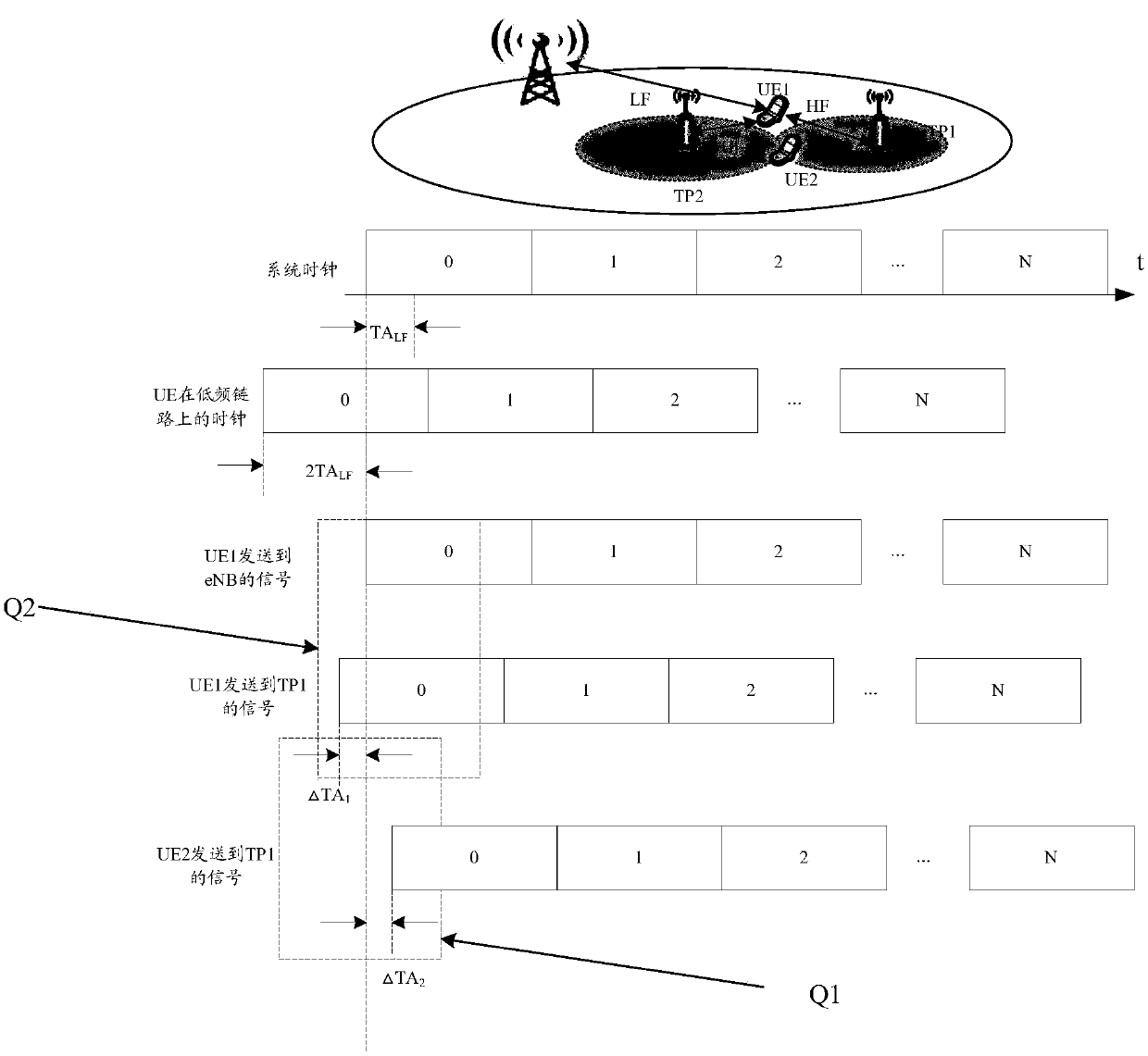
[0013] Q1: Although the terminal and the low-frequency macro station ( figure 1 The middle eNB) has completed the time synchronization and uplink timing advance process, namely figure 1 The clock on the network side and the signal sent by the UE to the eNB are aligned in time, but when the result is reused on the micro station, the uplink transmission signals of different terminals (UE1 and UE2 in the figure) arrive at a certain micro station (TP1 in the figure) There is a random delay difference, which will destroy the orthogonality of the uplink measurement reference signal in the time domain, and also cause interference to the data part of the reference measurement signal
[0014] Q2: On the other hand, even for a single terminal (UE1 in the figure), the result of time alignment with the macro station is multiplexed to the micro station (TP1 in the figure), and the low-frequency macro station will be caused by the different propagation distances of the paths. There is a delay difference between the high-frequency micro-station and the high-frequency micro-station. This delay difference will lead to the lack of beam detection, so that the reference signal sent by a certain beam cannot be completely received.
[0015] Therefore, in the HetNet hybrid networking scenario where the micro-station is a high-frequency base station and the macro-station is a low-frequency base station, the synchronization between the terminal and the macro-station and TA cannot be reused between the terminal and the high-frequency micro-station in the prior art, resulting in failure The problem of correctly transmitting the uplink reference signal, how to design an uplink reference signal transmission scheme to ensure the transmission accuracy of the uplink reference signal is an urgent problem to be solved

Method used


Image

  • A transmission method and device for an uplink reference signal
  • A transmission method and device for an uplink reference signal
  • A transmission method and device for an uplink reference signal

Examples


Embodiment 1

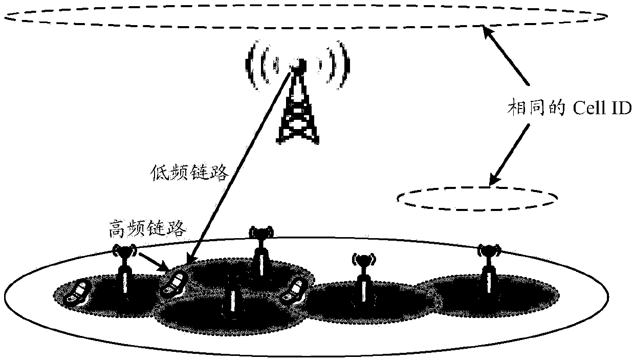
[0139] like Figure 10 As shown, embodiment one provides a kind of application figure 2 The shown mixed network of high-frequency micro-station and low-frequency macro-station or Figure 9 The frame structure in the communication system in which multiple high-frequency base stations are mixed networking is shown. Wherein, the high-frequency base station in the hybrid networking scenario of multiple high-frequency base stations may be a high-frequency macro station or a high-frequency micro station.

[0140] Figure 10 10 milliseconds are used as the frame length of a wireless frame; the wireless frame is composed of 10 wireless subframes with a frame length of 1 millisecond; a wireless subframe is divided into 8 subframes with a length of 0.125 milliseconds A time slot (time slot); wherein, each time slot consists of Q symbols, and the symbols may be single-carrier symbols or multi-carrier symbols, such as OFDM symbols. A typical Q value can be set to 7n, where n is a pos...

Embodiment 2

[0143] like Figure 11A and Figure 11B As shown, the second embodiment provides another application figure 2 The shown mixed network of high-frequency micro-station and low-frequency macro-station or Figure 9 The frame structure in the communication system in which multiple high-frequency base stations are mixed networking is shown. Wherein, the high-frequency base station in the hybrid networking scenario of multiple high-frequency base stations may be a high-frequency micro-station or a high-frequency macro-station.

[0144] like Figure 11A As shown, the difference from Embodiment 1 is that since the uplink reference signal is not continuous in the time domain resource, the NoMP intervals for transmitting the uplink reference signal are also distributed, and the NoMP interval is divided into several NoMP segments.

[0145] Figure 11B 10 milliseconds are used as the frame length of a wireless frame; the wireless frame is composed of 10 wireless subframes with a fram...

Embodiment 3

[0148] Based on the frame structures given in Embodiment 1 and Embodiment 2, Embodiment 3 provides a method for transmitting an uplink synchronization reference signal, and the method is applied to figure 2 The network deployment scenario shown, such as Figure 12 As shown, the specific steps include:

[0149] Step 121: The terminal completes synchronization with the low-frequency macro station based on the low-frequency link, and obtains the system clock on the network side and the uplink TA of the terminal on the low-frequency link.

[0150] Step 122: the terminal determines the time domain resource sending position of the uplink synchronization reference signal on the high frequency link.

[0151] The method of determining the sending position of time domain resources can use the system clock obtained by the low frequency link and / or the uplink TA value obtained by the terminal on the low frequency link, and use the starting point of a time slot of the low frequency link ...


PUM


Abstract

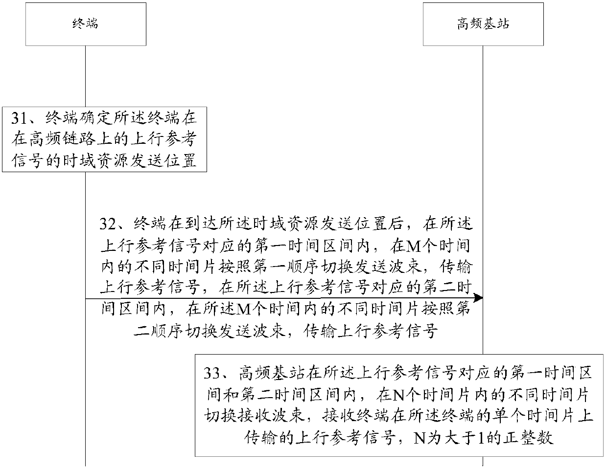
The invention discloses a transmission method and device for an uplink reference signal, so as to solve the problem that the uplink reference signal cannot be transmitted correctly and data transmission is affected in a hybrid networking scenario. The method is as follows: the terminal determines the time-domain resource transmission position of the uplink reference signal, and there is a guard interval at at least one end of the uplink reference signal; after the terminal arrives at the time-domain resource transmission position, within the first time interval corresponding to the uplink reference signal, within M Different time slices within a period of time switch the sending beams according to the first order, transmit the uplink reference signal, and in the second time interval corresponding to the uplink reference signal, switch the sending beams according to the second order during different time slices within the M times, and transmit An uplink reference signal, where the uplink reference signal includes uplink reference signals transmitted on M different time slices, so that accurate transmission of the uplink reference signal can be realized.

Description

technical field [0001] The present invention relates to the field of wireless technology, in particular to a method and device for transmitting an uplink reference signal. Background technique [0002] Hybrid networking of high and low frequency base stations, also known as Heterogeneous Network (HetNet) networking of high and low frequency base stations. Low frequency base stations cover a large area, and high frequency base stations provide hotspot coverage within the coverage of low frequency base stations to improve hotspot coverage. capacity of the region. Because this networking mode can take advantage of the wide coverage capabilities of low-frequency base stations to reduce the system overhead of high-frequency directional link transmission control signaling, it is a key deployment scenario for 5G in the future. [0003] In the existing LTE system, Softcell networking is a typical HetNet networking solution. Softcell networking, that is, the micro station (micro / pi...

Claims


Application Information

Patent Timeline
Patent Type & Authority Patents(China)
IPC IPC(8): H04J3/06H04W72/12
CPCH04W72/04H04W56/001H04W72/21H04L5/0048H04W24/10H04W72/0446
Inventor 曾昆王光健黄煌
Owner HUAWEI TECH CO LTD
Learn More