A tail gas recovery and reuse system and a tail gas recovery type farm

A tail gas recovery and tail gas technology, which is applied in the fields of application, poultry farming, climate change adaptation, etc., can solve the problems of environmental protection, tail gas heat recovery and utilization, environmental pollution, etc., and achieve the goals of protecting the environment, high utilization efficiency, and promoting plant growth Effect

Active Publication Date: 2021-05-04
盛宝富
View PDF8 Cites 0 Cited by
  • Summary
  • Abstract
  • Description
  • Claims
  • Application Information

AI Technical Summary

Problems solved by technology

[0003] The inventor found that in the prior art, the waste heat exhaust gas generated in the breeding room is usually directly discharged to the outside through the exhaust fan. On the one hand, the heat in the exhaust gas is not recycled, and on the other hand, it will cause certain environmental pollution. , very environmentally friendly

Method used


Image

  • A tail gas recovery and reuse system and a tail gas recovery type farm
  • A tail gas recovery and reuse system and a tail gas recovery type farm
  • A tail gas recovery and reuse system and a tail gas recovery type farm

Examples


no. 1 example

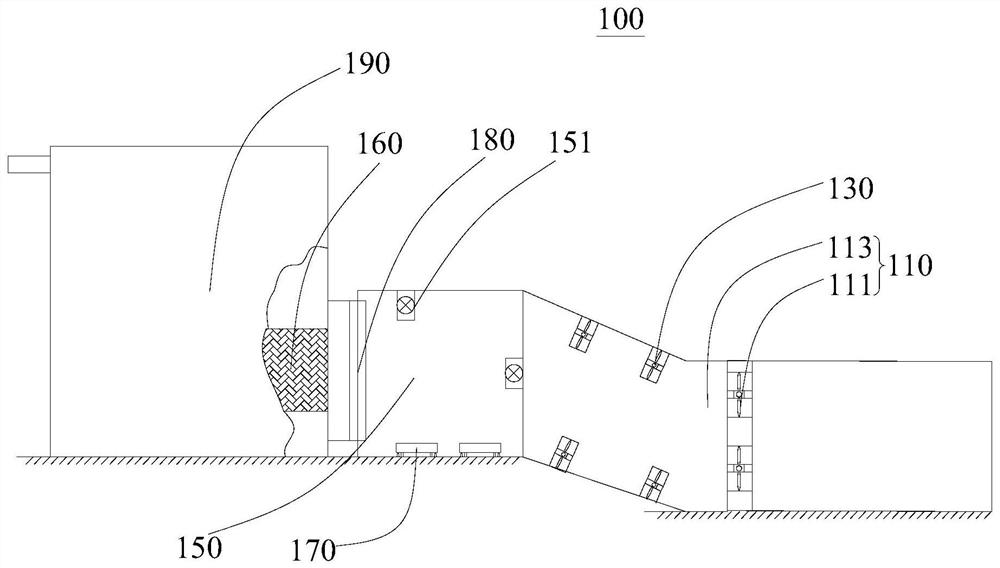
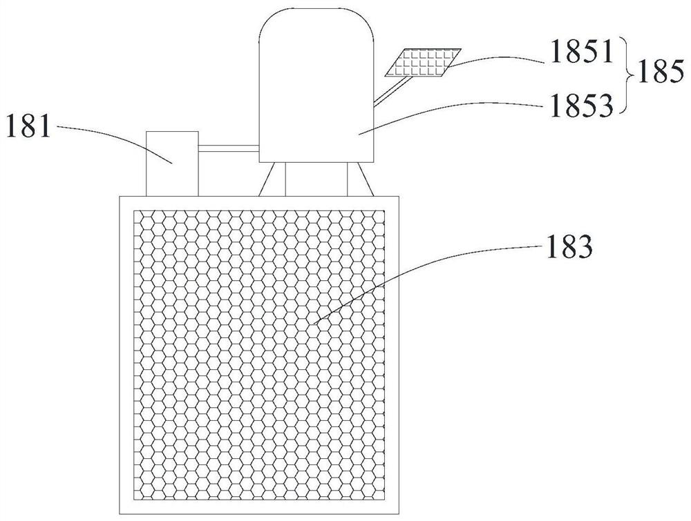
[0036] refer to figure 1 , the present embodiment provides a tail gas recovery and reuse system 100, which is used to install the tail gas discharge port of the breeding house and dry silage. Room 150, temperature control system 160, multiple feed turning devices 170, filter device 180 and constant temperature ecological greenhouse 190, multiple feed turning devices 170 are accommodated in drying room 150, constant temperature ecological greenhouse 190 is connected with drying room 150, The drying room 150 communicates with the tail gas collection device 110 through the air induction device 130, and the tail gas collection device 110 is installed at the tail gas discharge port of the breeding house, so that the tail gas produced by the breeding house enters the drying room through the tail gas collection device 110 and the air introduction device 130 150, and then enter the constant temperature ecological greenhouse 190.

[0037] In this embodiment, the drying room 150 also h...

no. 2 example

[0058] see Figure 6 , the present embodiment provides a tail gas recovery type farm 200, including a breeding room 210, a feed room 230, a temperature control system 160, a temperature measuring device (not shown) and a tail gas recycling system 100, and the temperature control system 160 is set In the breeding house 210 , the breeding house 210 is connected with the tail gas recycling system 100 . The feed room 230 is arranged beside the drying room 150 and is connected with the drying room 150 and the constant temperature ecological greenhouse 190 through a section road. The basic structure, principle and technical effects of the tail gas recovery and reuse system 100 are the same as those of the first embodiment. For a brief description, for parts not mentioned in this embodiment, reference may be made to the corresponding content in the first embodiment.

[0059] There are multi-layer breeding rooms in the breeding room 210, and breeding cages are set up in each layer of...


PUM


Abstract

The invention provides a tail gas recovery and reuse system and a tail gas recovery farm, which relate to the technical field of tail gas recovery. The tail gas recovery farm includes a breeding room, a feed room, and a tail gas recovery and reuse system, and the tail gas recovery and reuse system includes a tail gas collection device. , an air induction device, a drying room, a filter device and a constant temperature ecological greenhouse, and the exhaust gas collection device includes a plurality of air supply fans and a transition chamber, and a plurality of air supply fan arrays are arranged on one side of the transition chamber. The air induction device is set between the transition chamber and the drying room to send the tail gas into the drying room. The filter device includes a water injector and a filter screen curtain, the filter screen curtain is detachably installed at the air outlet, and the water injector is fixedly arranged on the top of the filter screen curtain. Compared with the prior art, the exhaust gas recovery and reuse system provided by the present invention can recover and reuse the exhaust gas, has high utilization efficiency, and protects the environment at the same time.

Description

technical field [0001] The invention relates to the technical field of tail gas recovery, in particular to a tail gas recovery and reuse system and a tail gas recovery farm. Background technique [0002] In the breeding industry, especially for the breeding of poultry and livestock, the exhaust gas produced when the poultry and livestock live in cages has always been a headache for farmers. Especially in poultry breeding, a large number of poultry are piled up in a relatively closed breeding room, which will produce a large amount of waste heat and exhaust gas. [0003] The inventor found that in the prior art, the waste heat exhaust gas generated in the breeding room is usually directly discharged to the outside through the exhaust fan. On the one hand, the heat in the exhaust gas is not recycled, and on the other hand, it will cause certain environmental pollution. , very environmentally friendly. [0004] In view of this, it is particularly important to design and manuf...

Claims


Application Information

Patent Timeline
Patent Type & Authority Patents(China)
IPC IPC(8): A01K1/00A01K31/00A01G9/24A23N17/00
CPCA01G9/24A01K1/00A01K1/0047A01K31/00A23N17/004A23N17/007Y02A40/25
Inventor 盛宝富
Owner 盛宝富
Why Eureka
Try Eureka