Supercharge Your Innovation With Domain-Expert AI Agents!

Drilling device for drilling hole in long channel steel

A technology for drilling devices and long grooves, which is applied in the direction of drilling/drilling equipment, feeding devices, driving devices, etc. It can solve the problems of low drilling efficiency, increased labor intensity, and large number of marks, etc., and achieves improved drilling efficiency. Efficiency, the effect of reducing labor intensity

Inactive Publication Date: 2018-02-02
甘肃远效科技信息咨询有限公司
View PDF0 Cites 4 Cited by
  • Summary
  • Abstract
  • Description
  • Claims
  • Application Information

AI Technical Summary

Problems solved by technology

The length of the channel steel is very long, and it is difficult to drill multiple equal-spaced installation holes at the bottom of the channel steel with an ordinary bench drill, because the supporting platform area of ​​the drill floor is small, and the two ends of the channel steel extend outside the drill floor If the two ends are unbalanced, the channel steel will fall from the drill floor, and it is easy to injure the workers who are operating the bench drill, which is very unsafe
After drilling a mounting hole, the channel steel must be moved, which is time-consuming and labor-intensive, which increases the labor intensity of workers
Moreover, before channel steel drilling, it is necessary to mark the line first, and then mark the drilling points. Due to the large number of marks, the labor intensity is increased and the drilling efficiency is low.
In addition, the waste chips generated during the drilling process are accumulated in the groove of the channel steel and cannot be discharged, resulting in the obstruction of drilling

Method used


Image

  • Drilling device for drilling hole in long channel steel
  • Drilling device for drilling hole in long channel steel

Examples


Embodiment Construction

[0013] The present invention will be further described below in conjunction with accompanying drawing, protection scope of the present invention is not limited to the following:

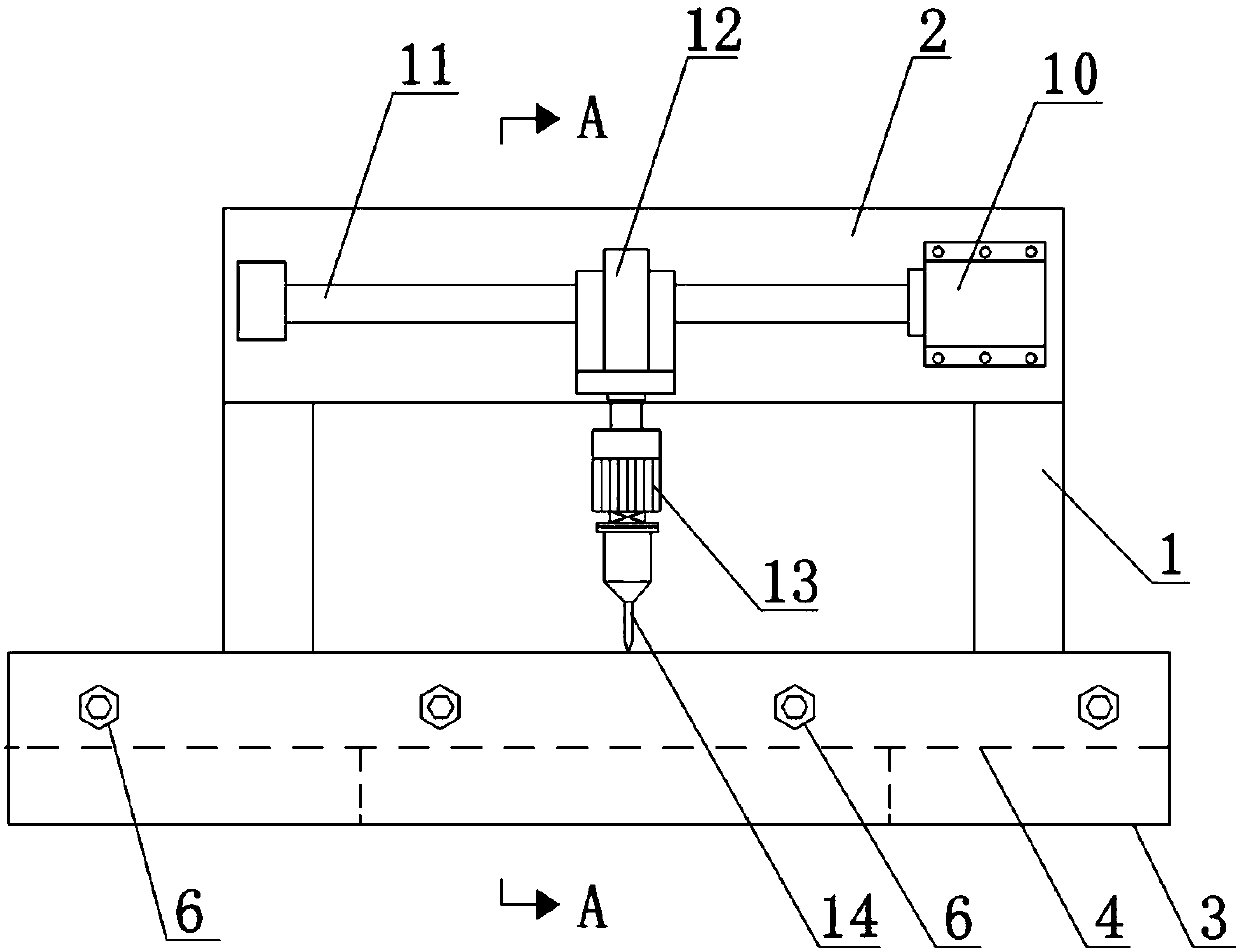
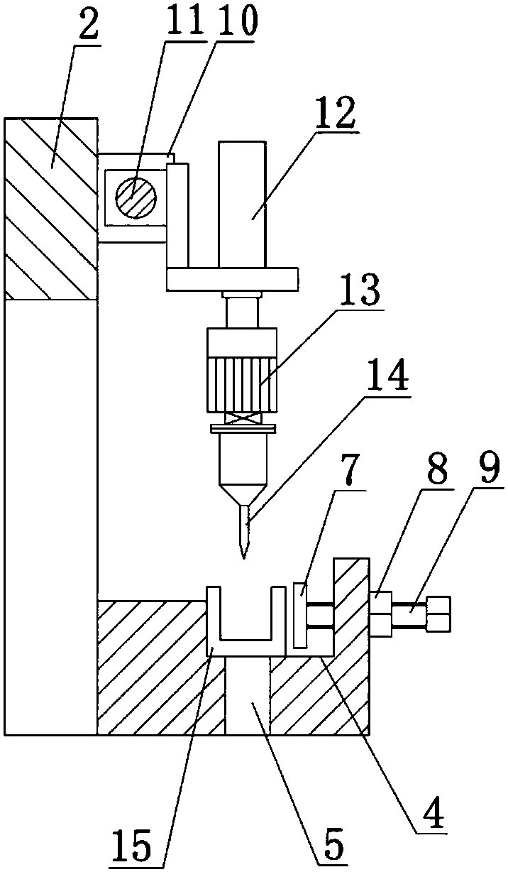
[0014] Such as Figure 1~2 Shown, a kind of drilling device that is used for drilling on the long channel steel, it comprises frame 1, the crossbeam 2 that arranges frame 1 top, is arranged on the supporting platform 3 of frame 1 front side, described supporting platform The top of 3 is provided with a horizontal groove 4, and the bottom of the support table 3 is provided with a chip discharge port 5 connected to the groove 4. The waste chips generated during the drilling process are directly discharged from the chip discharge port 5, avoiding waste chips Accumulated to ensure smooth drilling.

[0015] The front side of described supporting platform 3 and along its length direction are provided with channel steel locking mechanism 6, the spacing between adjacent two channel steel locking mechanisms ...


PUM


Abstract

The invention discloses a drilling device for drilling holes on long channel steel, which comprises a frame (1), a beam (2) arranged on the top of the frame (1), and a beam (2) arranged on the front side of the frame (1). The support platform (3), the front side of the support platform (3) is provided with a channel steel locking mechanism (6) along its length direction, and the channel steel locking mechanism (6) is fixed on the support platform by a pressing plate (7). (3) The locking nut (8) on the end face and the adjusting screw (9) connected with the locking nut (8) are composed of a vertically arranged oil cylinder (12) fixed on the nut, and the piston rod of the oil cylinder (12) A vertically arranged motor B (13) is fixed on the top, and the output end of the motor B (13) is connected with a drill bit (14), and the drill bit (14) is arranged towards the groove (4). The invention has the beneficial effects of reducing labor intensity of workers, improving drilling efficiency, drilling channel steels of different specifications, and being safe and reliable.

Description

technical field [0001] The invention relates to the technical field of drilling holes in channel steel, in particular to a drilling device for drilling holes in long channel steel. Background technique [0002] Channel steel is the most commonly used construction material on construction sites. The middle part of the bottom of the channel steel is drilled with a plurality of installation holes, and the channel steel can be installed on the body by passing the bolts through the installation holes and connecting with the threaded holes on the body. The length of the channel steel is very long, and it is difficult to drill multiple equal-spaced installation holes at the bottom of the channel steel with an ordinary bench drill, because the supporting platform area of ​​the drill floor is small, and the two ends of the channel steel extend outside the drill floor If the two ends are unbalanced, the channel steel will fall from the drill floor, and it is easy to hurt the workers ...

Claims


Application Information

Patent Timeline
IPC IPC(8): B23B39/14B23B47/06B23B47/22B23Q11/00B23Q5/40
CPCB23B39/14B23Q5/10B23Q5/26B23Q5/40B23Q11/0042
Inventor 张俭平
Owner 甘肃远效科技信息咨询有限公司
Features
  • R&D
  • Intellectual Property
  • Life Sciences
  • Materials
  • Tech Scout
  • Unparalleled Data Quality
  • Higher Quality Content
  • 60% Fewer Hallucinations
Learn More