Rotating and clamping type drilling machine for workpieces

A kind of processing machinery and clamping technology, which is applied in the direction of metal processing machinery parts, metal processing, boring/drilling, etc., can solve the problems of low efficiency, affecting processing quality, and poor workpiece clamping and fixing, so as to achieve a stable structure, Improve drilling efficiency and quality, facilitate the effect of workpiece processing

Inactive Publication Date: 2018-02-02
NANCHANG INST OF TECH
View PDF4 Cites 22 Cited by
  • Summary
  • Abstract
  • Description
  • Claims
  • Application Information

AI Technical Summary

Problems solved by technology

[0003] This kind of processing method not only has poor clamping and fixing of the workpiece, but also needs to repeatedly adjust the orientation of the workpiece on the fixture or adjust the position of the drilling device when drilling holes in different orientations of the workpiece. One clamping and fixing is only suitable for one drill. The processing of holes is inefficient and affects the processing quality

Method used


Image

  • Rotating and clamping type drilling machine for workpieces
  • Rotating and clamping type drilling machine for workpieces

Examples


Embodiment Construction

[0018] The following will clearly and completely describe the technical solutions in the embodiments of the present invention with reference to the accompanying drawings in the embodiments of the present invention. Obviously, the described embodiments are only some, not all, embodiments of the present invention. Based on the embodiments of the present invention, all other embodiments obtained by persons of ordinary skill in the art without making creative efforts belong to the protection scope of the present invention.

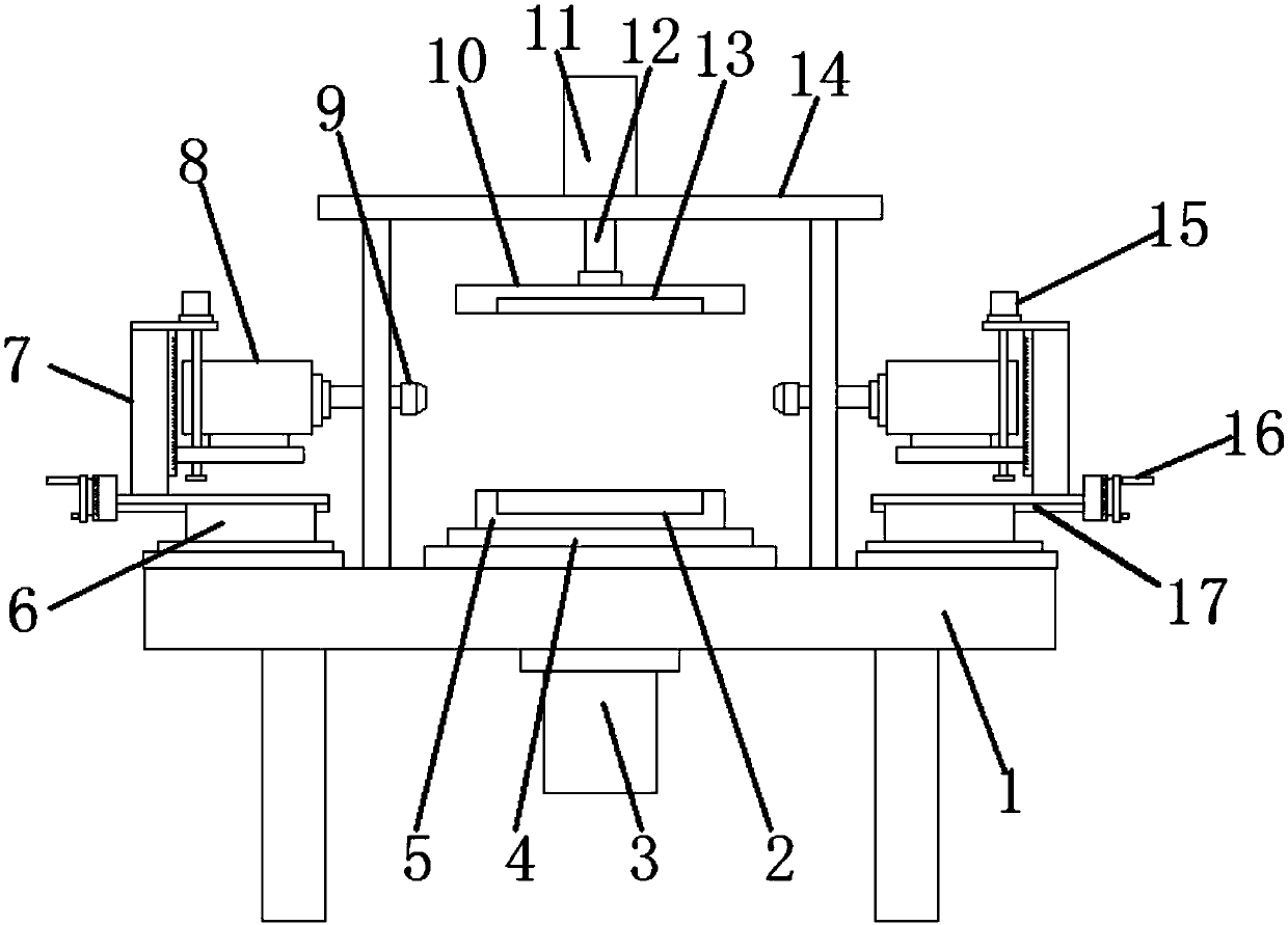
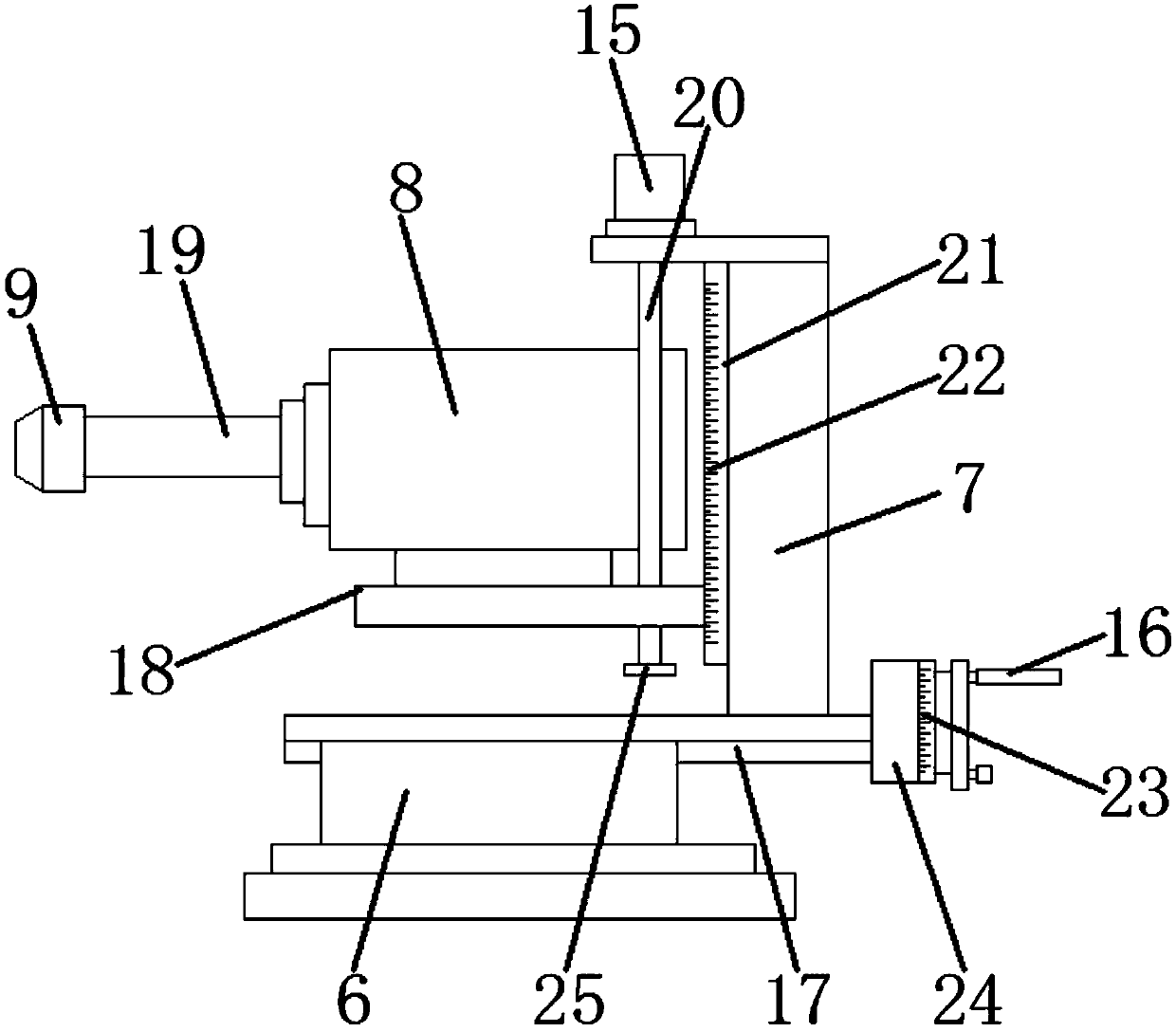
[0019] see Figure 1~2 , in an embodiment of the present invention, a workpiece rotating and clamping drilling machine includes a workbench 1, a rotating disk 5, a clamping disk 10, a transverse slide rail 17 and a lifting plate 18, and the upper end of the workbench 1 is connected to the gantry Frame 14, a hydraulic cylinder 11 is installed in the middle part of the top of the gantry frame 14, the hydraulic cylinder 11 is connected to the piston rod 12, the b...


PUM


Abstract

The invention discloses a rotating and clamping type drilling machine for workpieces. The rotating and clamping type drilling machine comprises a worktable, a rotary plate, a clamping plate, transverse sliding rails and lifting plates. The upper end of the worktable is connected with a gantry. A hydraulic cylinder is mounted in the middle of the top end of the gantry. The hydraulic cylinder is connected with a piston rod. The bottom end of the piston rod is connected with the clamping plate. An upper clamping groove is formed in the bottom of the clamping plate. The rotary plate is arranged below the clamping plate. A transverse adjusting block is connected to one end of each transverse sliding rail. A lifting stand column is mounted on the upper side of each transverse adjusting block. Alifting sliding rail is arranged on the side face of each lifting stand column. The lifting plates are slidably arranged in the lifting sliding rails. A lifting screw penetrates through each lifting plate. A drilling motor is mounted on each lifting plate. The drilling motors are connected with drilling bits through drilling rods. By the adoption of the rotating and clamping type drilling machinefor the workpieces, workpiece clamping and direction switching are achieved conveniently, machining of the workpieces is facilitated, and no multi-time clamping fixing and changing of the direction isneeded; and in cooperation with horizontal movement of transverse adjusting blocks and vertical movement of the lifting plates, the drilling work of the drilling bits is facilitated, and the drillingefficiency and quality are improved.

Description

technical field [0001] The invention relates to the technical field of drilling machines, in particular to a workpiece rotating and clamping drilling machine. Background technique [0002] When drilling a specific workpiece in the workpiece industry, it is necessary to use a three-jaw chuck (three circumferentially distributed claws, place one end of the workpiece at the center, and the three claws squeeze toward the center to clamp and position Workpiece) to clamp and position the workpiece, then determine the drilling position on the fixed workpiece, and then adjust the tool to the corresponding drilling position for drilling and drilling. [0003] This kind of processing method not only has poor clamping and fixing of the workpiece, but also needs to repeatedly adjust the orientation of the workpiece on the fixture or adjust the position of the drilling device when drilling holes in different directions of the workpiece. One clamping and fixing is only suitable for one dr...

Claims


Application Information

Patent Timeline
Patent Type & Authority Applications(China)
IPC IPC(8): B23B39/22B23Q7/02B23Q3/08
CPCB23B39/22B23Q3/082B23Q7/02
Inventor 洪琦
Owner NANCHANG INST OF TECH
Why Eureka
Try Eureka