Check patentability & draft patents in minutes with Patsnap Eureka AI!

Sludge circulating filtration integrated reactor and sewage treatment method

A sludge circulation and reactor technology, applied in water/sludge/sewage treatment, chemical instruments and methods, biological water/sewage treatment, etc., can solve the problems of turbidity of factory water and low sludge concentration, and meet the guaranteed standards or reuse, high biomass, and strong resistance to changes in water quality and quantity

Inactive Publication Date: 2018-02-02
HARBIN INST OF TECH
View PDF4 Cites 0 Cited by
  • Summary
  • Abstract
  • Description
  • Claims
  • Application Information

AI Technical Summary

Problems solved by technology

[0006] The purpose of the present invention is to solve the existing problems of low sludge concentration and turbidity of factory water, and provide a sludge circulation and filtration integrated reactor and a method for sewage treatment, which is suitable for urban sewage, water quality and water volume fluctuations Treatment of large village sewage, scattered villas, tourist areas and low-concentration organic industrial wastewater with similar water quality

Method used


Image

  • Sludge circulating filtration integrated reactor and sewage treatment method
  • Sludge circulating filtration integrated reactor and sewage treatment method
  • Sludge circulating filtration integrated reactor and sewage treatment method

Examples


specific Embodiment approach 1

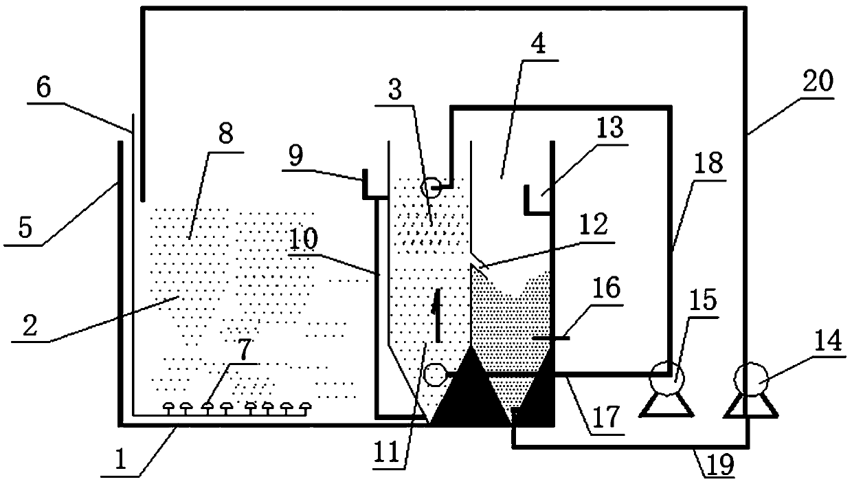
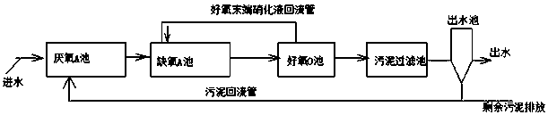
[0020] Specific implementation mode one: as image 3 As shown, this embodiment describes an integrated reactor for sludge circulation and filtration. The integrated reactor includes a box body 1, and aerobic activated sludge areas are arranged in the box body 1 from left to right. 2. Sludge circulation filter area 3 and water outlet area 4, the aerobic activated sludge area 2 contains activated sludge 8, and the left side of the aerobic activated sludge area 2 is provided with a water inlet pipe 5 and a blower air pipe 6 One end of the blower air pipe 6 communicates with the aeration head 7 arranged at the bottom of the aerobic activated sludge area 2, and one end of the water inlet pipe 5 communicates with the top of the aerobic activated sludge area 2, and the aerobic activated sludge The right side of area 2 is provided with a diversion pipe 10, the upper end of the diversion pipe 10 is provided with a sludge degassing weir 9, the lower end of the diversion pipe 10 communic...

specific Embodiment approach 2

[0021] Embodiment 2: The sludge circulation and filtration integrated reactor described in Embodiment 1, the tank 1 of the reactor is rectangular, square or cylindrical in shape.

specific Embodiment approach 3

[0022] Embodiment 3: The sludge circulation and filtration integrated reactor described in Embodiment 1 or 2, the tank 1 of the reactor is made of steel, glass fiber reinforced plastic, plexiglass or PP material.

[0023] Embodiment 4: In Embodiment 1, an integrated reactor for sludge circulation and filtration, the sludge circulation and filtration layer 11 is provided with a water distribution plate or a water distribution pipe.


PUM


Abstract

The invention relates to a sludge circulating filtration integrated reactor and a sewage treatment method, and belongs to the technical field of sewage treatment. The integrated reactor comprises a box body, and an aerobic activated sludge area, a sludge circulating filtration area and a water outlet area are sequentially arranged in the box body from left to right; when sewage treatment is carried out, sewage flows through the sludge circulating filtration integrated reactor from left to right. The reactor has the advantages that the high activated sludge concentration (up to 4500-5000 mg / L)can be maintained, effluent is clean after sludge filtration, and the treated water quantity meets the primary A standard of the discharge standard of pollutants for municipal wastewater treatment plant (GB 18918-2002). Through hydraulic circulation, continuous updating of a sludge layer is kept, and interception of microorganisms and clarification and filtration of water are completed, so that the bioreactor has the advantages of being high in biomass retention, small in equipment size and efficient in mud-water separation.

Description

technical field [0001] The invention belongs to the technical field of sewage treatment, and in particular relates to an integrated reactor for sludge circulation and filtration and a method for sewage treatment. Background technique [0002] The domestic sewage produced by towns and villages contains organic matter and nitrogen and phosphorus pollutants. If not properly disposed of, it will pollute the receiving water body. In order to improve the water environment quality of urban residents, the government requires urban and village sewage to meet the first-class A standard of the "Pollutant Discharge Standards for Urban Sewage Treatment Plants" (GB 18918-2002). As far as the current use of domestic sewage treatment processes in our country is concerned, the AAO synchronous denitrification and phosphorus removal process that continuously flows into the water is the main one. [0003] Pollutants in domestic sewage mainly include organic matter (often represented by chemica...

Claims


Application Information

Patent Timeline
IPC IPC(8): C02F3/12C02F101/30C02F101/16
CPCC02F3/1221C02F2101/16C02F2101/30C02F2203/006C02F2301/046Y02W10/10
Inventor 陈志强温沁雪
Owner HARBIN INST OF TECH
Features
  • R&D
  • Intellectual Property
  • Life Sciences
  • Materials
  • Tech Scout
  • Unparalleled Data Quality
  • Higher Quality Content
  • 60% Fewer Hallucinations
Learn More