Intelligent external inspection and maintenance vehicle for rail beam of suspension monorail transit

A monorail transportation, inspection and maintenance technology, applied in railway inspection vehicles, tracks, roads, etc., can solve problems such as poor sealing of track beam joints, manual maintenance of track beams, and cracks in track beams, and achieve the effect of improving maintenance efficiency.

Pending Publication Date: 2018-02-02
CHINA RAILWAY ERYUAN ENG GRP CO LTD +2
0 Cites 16 Cited by

AI-Extracted Technical Summary

Problems solved by technology

Due to the long-term exposure of the steel track beam to the natural environment, on the existing test line, there are often problems such as cracks, corrosion, loose bo...

Abstract

Suspended monorail traffic track beam external intelligent inspection and maintenance vehicle to realize the automation, informatization and intelligence of track beam external faults and defect inspections, and provide inspection and maintenance operating conditions. It has a car body, a drive unit, an intelligent detection unit, a driving control unit and a safety protection unit. The drive unit is composed of a power storage battery and a suspension bogie. The rear of the car body is equipped with a suspended monorail track beam inspection and maintenance operation platform, which is equipped with a sensor lifting bracket, a contour detector, a lifting fence translation track, an inspection and maintenance operation lifting platform, a limit detection laser sensor, and a corrosion detection camera; the suspended monorail The track beam inspection and maintenance work platform can move laterally and vertically on the translation track of the lifting fence, and the range of motion covers the left, right and lower sides of the track beam, providing an inspection and maintenance platform that can be moved horizontally and vertically outside the track beam. The contour detector and the corrosion detection camera of the intelligent detection system are installed on the vertically movable sensor lifting brackets on both sides of the middle of the car body, the corrosion detection camera is installed outside the middle of the bracket, and the contour detector is installed on the inside of the middle and top of the bracket .

Application Domain

Railway inspection trolleysRailway tracks +1

Technology Topic

Image

  • Intelligent external inspection and maintenance vehicle for rail beam of suspension monorail transit
  • Intelligent external inspection and maintenance vehicle for rail beam of suspension monorail transit
  • Intelligent external inspection and maintenance vehicle for rail beam of suspension monorail transit

Examples

  • Experimental program(1)

Example Embodiment

[0014] The present invention will be further described below in conjunction with the drawings and embodiments.
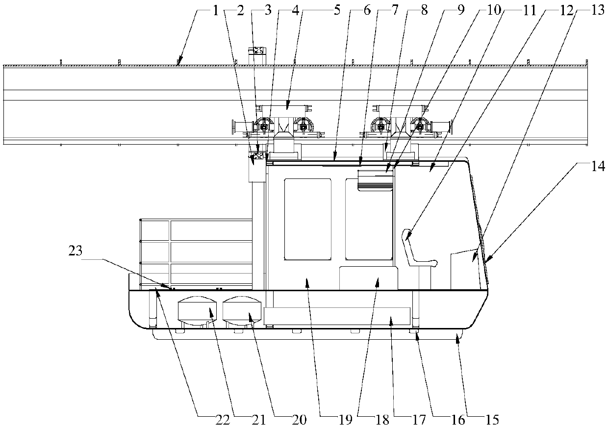
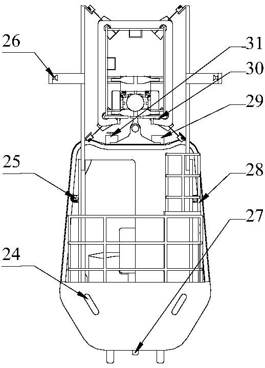
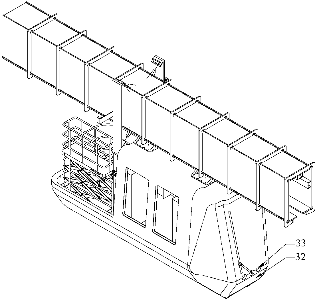
[0015] See Figure 1 to Figure 4 The external intelligent inspection and maintenance vehicle for suspended monorail transit track beams of the present invention includes an inspection vehicle frame 4, an inspection vehicle housing 6, a driving unit, a driving control unit, an intelligent detection unit and a safety protection unit.
[0016] The driving unit is mainly composed of a suspended bogie 5 and a power battery 17.
[0017] The driving control unit is mainly composed of a programmable logic controller (PLC) and an industrial computer.
[0018] The intelligent detection unit is mainly composed of a contour detector 3, a limit detection laser sensor 25, a rust detection camera 26, and a sensor lifting bracket 2.
[0019] The main functional unit of the contour detector 3 is a high-precision laser displacement sensor; the laser transmitter shoots the visible red laser to the surface of the object to be measured through the lens, and the laser reflected by the object passes through the receiver lens and is received by the internal CCD linear camera According to different distances, the CCD linear camera can "see" this light spot at different angles. Based on this angle and the known distance between the laser and the camera, the digital signal processor can calculate the distance between the sensor and the measured object. The system uses four sets of laser sensors to capture the 3D data points of the track profile that they return, and then stores the data in the form of data clouds in the memory, and uses the data regular gridding algorithm to convert the discrete data point clouds in the memory. Perform surface fitting, and divide the point cloud data value according to a certain threshold. When the data displacement value exceeds the threshold, the system distinguishes the surface at that place with different colors to detect the presence outside the track Defects. The system displays the fitted track surface contour time and time to the interface of the industrial computer, and divides the data into two. One data is sent to the control center by TCP/IP network data transmission, and the other data is used for itself The data is saved and stored in the industrial computer.
[0020] The car body is divided into three parts. The front end is the driver’s cab with a console 13; the middle part is the passenger compartment 19, which is equipped with interior lighting 7, on-board air conditioner 9, and tool cabinet 18; at the end is a suspended monorail track The beam inspection maintenance work platform 22 is provided with a sensor lifting bracket 2, a contour detector 3, a lifting fence translation track 23, a boundary detection laser sensor 25, and a rust detection camera 26.
[0021] The boundary detection laser sensor 25 is provided with four groups, which are respectively installed on the left upper and lower two groups and the right upper and lower groups of the external inspection vehicle; mainly to detect whether there is foreign object intrusion limit. Its main working principle is: before the external inspection vehicle starts, the limit detection laser sensor 25 can be set to the position threshold. When the equipment is started, the limit detection laser sensor 25 starts to work. The inspection vehicle is running, if there are obstacles Within the threshold set by the sensor, the sensor sends a switch value to the PLC, indicating that there are currently unknown objects in the threshold area, so as to detect the external limit of the inspection equipment operation.
[0022] The rust detection camera 26 is equipped with two, the detection end program mainly runs in the inspection equipment industrial computer, and the main content of the detection includes weld crack width, crack length, rust surface area, boundary, etc. The system collects external pictures of the track beam through machine vision intensively, and performs algorithmic processing on the collected pictures through the software of the detection unit. The algorithm is based on sparse representation to detect defects. For the detection of defects such as rust and cracks, first use the "sliding frame" method to slide the entire picture to obtain the first and second moments of each picture, and then combine the first and second moments to roughly classify the blocks. For normal blocks and suspected defective blocks, the classification method is also based on the overall situation, that is, to sort the obtained blocks. If there is a jump in the sorted result, then the image block is roughly classified according to the jump point. Then the normal block and the suspected defective block can be analyzed; then the normal block is quickly feature extracted through the generalized Haar feature, and the generalized Haar feature is compressed by means of compressed sensing, and the extracted feature is used to classify the suspected defective block To get whether the current image is a qualified image. And the calculation result is divided into two, one piece of data is sent to the control center by TCP/IP network data transmission, and the other piece of data is used for its own data storage and stored in the industrial computer.
[0023] The sensor lifting bracket 2 is installed on both sides of the car body, including the bracket body, stepping motor, lead screw, sliding table, stroke limit sensor, contour detector 3, limit detection laser sensor 25, rust detection camera 26 installation In the sliding table, when working, the stepping motor drives the screw to rotate, driving the sliding table to move up and down, until the stroke limit sensor has a signal input, the stepping motor stops, and the designated working position is reached at this time.
[0024] The safety protection unit includes a taillight and a tail ultrasonic radar 24, a front ultrasonic radar 33, and a bottom flashlight 16 which are connected to the driving control unit; the ultrasonic radar uses a transmitting probe to emit a certain frequency of ultrasonic waves, and then the receiving probe receives and transmits through obstacles. The returned ultrasonic wave is processed by the MCU in the control unit to calculate the distance according to the time difference between transmission and reception, so that the distance of the obstacle can be detected to avoid the collision of the "overhaul vehicle" with the obstacle in front, and the bottom flashing light 16 Warn ground personnel that the engineering vehicle is in operation.
[0025] The inspection vehicle frame 4 is mainly divided into a driver's cab 11, a passenger compartment 19, and a suspended monorail track beam inspection and maintenance work platform 22, and each part is separated by a partition 10 in the vehicle.
[0026] The driver's cab 11 is provided with an interior lighting lamp 7, a console 13, and a driver seat 12, and a windshield wiper 14 is installed.
[0027] The passenger compartment 19 is provided with an interior lighting lamp 7, a vehicle air conditioner 9 and a tool cabinet 18.
[0028] The suspended monorail track beam inspection and maintenance work platform 22 is provided with a sensor lifting bracket 2, a contour detector 3, a lifting fence translation track 23, a boundary detection laser sensor 25, and a rust detection camera 26.
[0029] The driving unit is mainly a suspended bogie 5, which includes a bogie body, driving wheels, guide wheels, transmission boxes, and a DC motor. The DC motor is connected to a double-outlet reducer, and the output shaft is connected to a clutch to drive The wheels are driven, and the bogie body is equipped with a spring damping independent suspension; a total of 8 guide wheels are divided into two groups, at least one group is attached to the inner wall of the track beam during operation.
[0030] The inspection vehicle frame 4 and the suspension bogie 5 are connected to the vehicle body connector 8 through the bogie.
[0031] The inspection and maintenance work lifting platform 28 is installed on the suspended monorail track beam inspection and maintenance work platform 22, and includes a hydraulic station 20, a working platform, a telescopic cross bracket, a sliding table, a lead screw, a lifting fence translation rail 23, a DC motor, Translation track limit sensor and translation track locking device. When working, the DC motor drives the lead screw to rotate, and the lead screw drives the sliding table to move along the translational rail 23 of the lifting fence until the translational rail limit sensor has a signal input, the motor stops, the locking device acts, and then the staff stands on the working platform and works The platform is raised and lowered in the vertical direction, and the staff sends an order to stop or continue to raise and lower. At the same time, the PLC calculates the current position of the platform by reading the number of rotations of the hydraulic pump to prevent accidents.
[0032] The jacking support 15 is used when the inspection trolley moves.
[0033] The power battery 17 adopts a lithium iron phosphate battery, which has the advantages of high safety performance, long life, good high temperature performance, large capacity, light weight and environmental protection.
[0034] The tool cabinet 18 in question is used to store tools required by the staff for maintenance.
[0035] The compressed air station 21 provides power for maintenance tools.
[0036] The working principle of the positioning system is that the PLC reads the number of pulses returned from the encoder disc in real time, and then multiplies it with the displacement value per pulse to obtain the real-time displacement value of the trolley, and the real-time speed of the trolley can be obtained according to the number of pulses per second. At the same time, an electronic label 30 is pasted along the outer wall of the track to correct the displacement of each section and reduce the accumulated error.
[0037] The electronic tag antenna 29 is installed on the top of the inspection vehicle housing 6.
[0038] The console 13 is equipped with a touch screen for displaying and controlling the state of the trolley.
[0039] The vehicle body position locking device 31 is used to prevent the inspection vehicle from sliding freely when the inspection vehicle stops on the track of the track beam when workers need to inspect and maintain the track beam.
[0040] The operation process of the external intelligent inspection and maintenance vehicle for the suspended monorail transit track beam of the present invention is as follows: the driving control unit is activated in the cab 11, the intelligent inspection and maintenance vehicle is in the standby state, the intelligent detection unit is turned on, and the interior of the vehicle is started when the light conditions are insufficient Illumination lamp 7, exterior lighting, bottom flash 16, the intelligent detection system including contour detector 3, limit detection laser sensor 25, rust detection camera 26 is adjusted to a reasonable detection position manually or automatically, and the intelligent inspection and maintenance vehicle is started. Automatic inspection and identification of welding seams, cracks, deformation and other problems on the outer side of the track beam in the maintenance area, and the system records the fault location and fault problems. The maintenance tools and materials can be sent to the problem point by automatic or manual operation of the maintenance work lifting platform 28 .
[0041] The above description is only to illustrate some principles of the present invention for the intelligent inspection and maintenance vehicle for the exterior of the suspended monorail transit track beam. It is not intended to limit the present invention to the specific structure and scope of application shown and described. The corresponding modifications and equivalents used belong to the scope of the patent applied for by the present invention.

PUM

no PUM

Description & Claims & Application Information

We can also present the details of the Description, Claims and Application information to help users get a comprehensive understanding of the technical details of the patent, such as background art, summary of invention, brief description of drawings, description of embodiments, and other original content. On the other hand, users can also determine the specific scope of protection of the technology through the list of claims; as well as understand the changes in the life cycle of the technology with the presentation of the patent timeline. Login to view more.

Similar technology patents

Classification and recommendation of technical efficacy words

Why Eureka
Try Eureka