Honeycomb beam
A technology of honeycomb beams and webs, applied in the direction of joists, girders, trusses, etc., to achieve the effects of uniform stress distribution, simple alignment of welding surfaces, and reduction of maximum stress values
- Summary
- Abstract
- Description
- Claims
- Application Information
AI Technical Summary
Problems solved by technology
Method used
Image


Examples
Embodiment 1
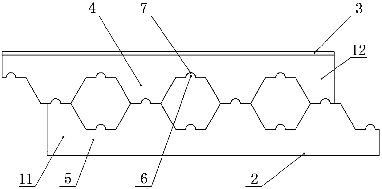
[0024] A cellular beam such as Figure 1~2 As shown, it includes a web 1, a first flange 2 and a second flange 3, the web 1 is divided into a first web 11 and a second web 12 by a cutting line, the first web 11 and the first The flange 2 is connected, and the second web 12 is connected with the second flange 3. The first web 11 and the second web 12 are divided into a pier 4 with a wider web and a pier 4 with a narrower web by the cutting line. The bridge part 5 , the junction of the pier part 4 and the bridge part 5 is the bridge toe 8 . The cutting line bends at the center of the corresponding position between the pier portion 4 of the first web 11 and the bridge portion 5 of the second web 12 to form a raised portion 6 extending from the first web 11 to the second web 12 and The recessed part 7 on the second web 12 correspondingly cooperates with the raised part 6 , and the cutting line bends at the center of the corresponding position between the bridge part 5 of the firs...
Embodiment 2
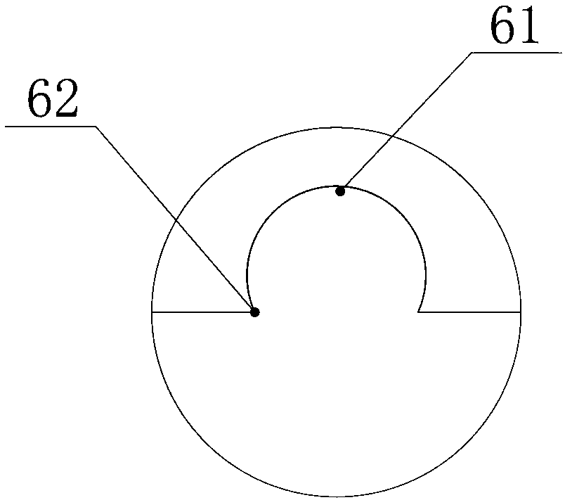
[0027] On the basis of the solution in Embodiment 1, the raised portion 6 is divided into a terminal head 61 and a convex neck 62 , and the maximum width of the terminal head 61 is slightly larger than the width of the convex neck 62 .
[0028] Since the biggest problem in the manufacturing process of honeycomb beams is deformation, there are many factors that cause deformation, such as the quality problems of H-shaped steel itself, deformation caused by transportation, deformation caused by welding stress, etc. Among them, the deformation caused by welding stress The deformation is the most serious. The so-called welding stress is the stress generated by the components due to cutting and welding. The inhomogeneous temperature field in the cutting and welding process and the local plastic deformation caused by it and the organization with different specific volumes are the root causes of welding stress and deformation. There are six main forms of honeycomb beam welding deforma...
Embodiment 3
[0034] On the basis of any one of embodiment 1 or 2, such as Figure 5-6 As shown, the junction of the cutting line between the pier 4 and the bridge 5 on the web 1 (that is, the position of the bridge toe 8) adopts an arc segment for a smooth transition. Here, "pier portion and bridge portion" refer to adjacent pier portions and bridge portions on the same web (ie, the first web or the second web).
[0035] Since the maximum normal stress of the honeycomb beam appears at the bridge toe, in order to prevent the fatigue life of the bridge toe from being reduced due to stress concentration, this embodiment adopts an arc segment transition at the bridge toe when designing the cutting line, which is different from the traditional folding Compared with the line segment, it can effectively reduce the maximum stress value and stress concentration at the bridge toe, and the stress distribution is more uniform.
PUM
| Property | Measurement | Unit |
|---|---|---|
| Arc angle | aaaaa | aaaaa |
Abstract
Description
Claims
Application Information
 - R&D
- Intellectual Property
- Life Sciences
- Materials
- Tech Scout
- Unparalleled Data Quality
- Higher Quality Content
- 60% Fewer Hallucinations
Browse by: Latest US Patents, China's latest patents, Technical Efficacy Thesaurus, Application Domain, Technology Topic, Popular Technical Reports.
© 2025 PatSnap. All rights reserved.Legal|Privacy policy|Modern Slavery Act Transparency Statement|Sitemap|About US| Contact US: help@patsnap.com