Method for calibrating parabolic reflex camera by using properties of conjugate diameters of straight line and circle

A conjugate diameter, catadioptric technology, applied in the field of computer vision, can solve problems such as degradation, and achieve the effect of simple production

Inactive Publication Date: 2018-02-02
YUNNAN UNIV
View PDF4 Cites 9 Cited by
  • Summary
  • Abstract
  • Description
  • Claims
  • Application Information

AI Technical Summary

Problems solved by technology

But the theory and calibration method in this literature is degenerate for the case of parabolic catadioptric camera

Method used


Image

  • Method for calibrating parabolic reflex camera by using properties of conjugate diameters of straight line and circle
  • Method for calibrating parabolic reflex camera by using properties of conjugate diameters of straight line and circle
  • Method for calibrating parabolic reflex camera by using properties of conjugate diameters of straight line and circle

Examples


Embodiment

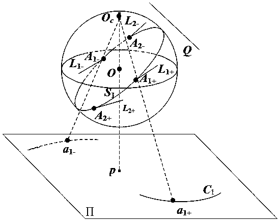
[0051] The invention proposes a method for linearly determining the internal parameters of a parabolic catadioptric camera by using a straight line as a target. The schematic structural diagram of the experimental template adopted in the present invention is as follows: figure 1 shown. The embodiments of the present invention will be described in more detail below with an example.

[0052] The experimental template used in the calibration of a parabolic catadioptric camera based on a straight line in space is a straight line in space, such as figure 1 As shown, the straight line is denoted as Q. Using the method of the present invention to calibrate the parabolic catadioptric camera used for the experiment, the specific steps are as follows:

[0053] 1. Fitting the image boundary and target curve equation

[0054] The image size used in the present invention is 1800×1700. Use the parabolic catadioptric camera to take three experimental images of the target, read the image...


PUM


Abstract

The present invention discloses a method for calibrating a parabolic reflex camera by using the properties of conjugate diameters of a straight line and a circle. Firstly, an edge point of a target image and an edge point of a mirror contour projection of one image are extracted from three images, and the mirror contour projection is obtained by least square fitting. A point is taken on a line image, and an antipodal image point is obtained. An intersection of a tangent of the image point to a line image and a tangent of the antipodal image point to the line image is a vanishing point. Two heterogeneous points are taken on the line image, two vanishing points are obtained, and a vanishing line is determined by the two vanishing points. An intersection of a polar of the vanishing points tothe line image and the vanishing line and the vanishing points form a group of orthogonal vanishing points, and six groups of orthogonal vanishing points are provided by the three images. Finally, theconstraint of an absolute quadratic curve image with the orthogonal vanishing points is used to solve camera internal parameters.

Description

technical field [0001] The invention belongs to the field of computer vision, and relates to a method for calibrating a parabolic catadioptric camera by utilizing the properties of a straight line and a conjugate diameter of a circle in space. Background technique [0002] The central task of computer vision is to understand images, and its ultimate goal is to enable computers to have the ability to recognize three-dimensional environmental information through two-dimensional images. This capability will not only enable machines to perceive the geometric information of objects in a three-dimensional environment including shape, posture, motion, etc., but also describe, store, recognize and understand them. Camera calibration is to determine the mapping relationship from three-dimensional space points to its two-dimensional image points, which is an essential step in many computer vision applications. In order to determine this mapping process, a geometric imaging model of t...

Claims


Application Information

Patent Timeline
Patent Type & Authority Applications(China)
IPC IPC(8): G06T7/80G06T7/13
CPCG06T7/13G06T7/80
Inventor 李远珍赵越
Owner YUNNAN UNIV
Why Eureka
Try Eureka