
Protection circuit and method against POE power supply error-plugging

A technology for protecting circuits and mis-plugging, applied in the field of communications, can solve problems such as terminal equipment damage, and achieve the effects of fewer circuit components, reduced equipment damage, and low cost

Pending Publication Date: 2018-02-02
COMBA TELECOM SYST CHINA LTD
View PDF6 Cites 3 Cited by
  • Summary
  • Abstract
  • Description
  • Claims
  • Application Information

AI Technical Summary

Problems solved by technology

[0003] The present invention provides a protection circuit and method for preventing misplugging of POE power supply, which are used to solve the problem of damage to terminal equipment caused by high voltage current generated by misplugging of POE power supply

Method used


Image

  • Protection circuit and method against POE power supply error-plugging
  • Protection circuit and method against POE power supply error-plugging
  • Protection circuit and method against POE power supply error-plugging

Examples


Embodiment 1

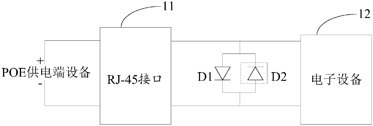
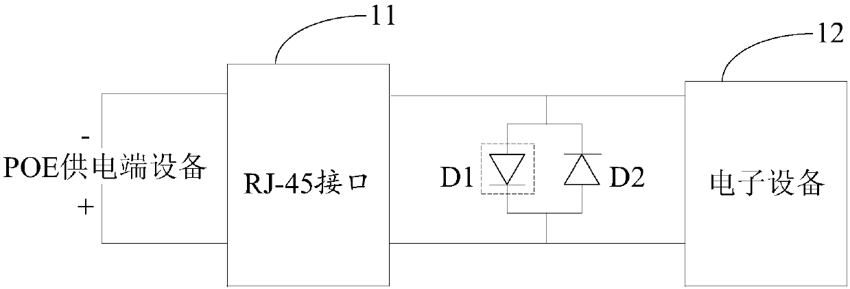
[0042] Such as Figure 1a As shown, the embodiment of the present invention provides a protection circuit for preventing misplugging of POE power supply. When the POE power supply end device is connected to the electronic device 12 through the data transmission pin in the RJ-45 interface 11, wherein the electronic device 12 The rated voltage is less than the power supply voltage of the POE power supply end equipment, the protection circuit includes:

[0043] a first diode D1;

[0044]The second diode D2, the anode of the second diode D2 is connected to the cathode of the first diode D1, the cathode of the second diode D2 is connected to the cathode of the first diode D1 The positive pole is connected to form a parallel structure; the parallel structure is arranged between the connection between the RJ-45 interface 11 and the electronic device 12, and one end of the parallel structure is connected to the POE power supply terminal through the RJ-45 interface 11 The positive vol...

Embodiment 2

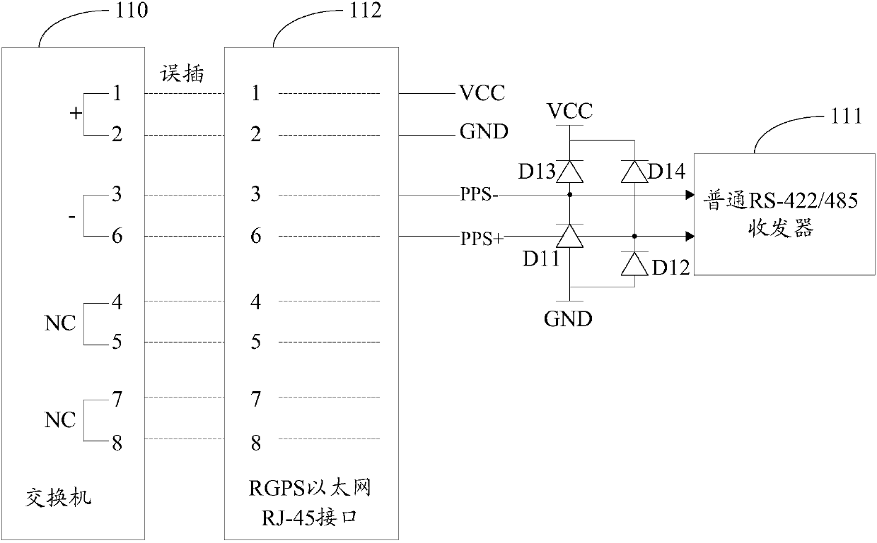
[0057] Such as Figure 2a Shown, embodiment two is on the basis of embodiment one, when a pin in the RJ-45 interface (such as Figure 2b The pin 1) of the RGPS Ethernet RJ-45 interface 123 in the middle is connected with the power supply, and the protection circuit and method also include:

[0058] a third diode D3, the third diode D3 is connected between the RJ-45 interface 21 and the power supply 23, wherein the anode of the third diode D3 is connected to the power supply 23, The negative pole is connected to the one pin in the RJ-45 interface 21 .

[0059] Specifically, such as Figure 2b As shown, the POE power supply end device is a switch 120, and the electronic equipment is a common RS-422 / 485 transceiver 121 and a common RS-422 / 485 transceiver 122. Pin is connected with common RS-422 / 485 transceiver 121 and common RS-422 / 485 transceiver 122, the interface of exchange 110 is mistakenly inserted into RGPS Ethernet RJ-45 interface 123 as an example, the effect of diode...

Embodiment 3

[0067]An embodiment of the present invention provides a base station, such as Figure 3a As shown, the base station includes an RJ-45 interface 31 and an electronic device 32. When the POE power supply terminal device 33 is connected to the electronic device 32 through the RJ-45 interface 31, the rated voltage of the electronic device 32 is lower than that of the POE power supply The power supply voltage of the end device 33, the base station also includes:

[0068] A capacitor 34 arranged between the RJ-45 interface 31 and the electronic device 32, the capacitor 34 is connected to the positive voltage pin or the negative voltage pin of the POE power supply terminal device 33 through the RJ-45 interface 31 .

[0069] Specifically, such as Figure 3b As shown, the POE power supply end device is a switch 301, and the electronic equipment is a common RS-422 / 485 transceiver 302 and a common RS-422 / 485 transceiver 303. Pins are connected with common RS-422 / 485 transceiver 302 an...


PUM


Abstract

The invention discloses a protection circuit and method against POE power supply error-plugging for preventing damage on terminal equipment from high voltage current caused by POE power supply error-plugging. A POE power supply device is connected with electronic equipment through data transmission pins in an RJ-45 interface, wherein the nominal voltage of the electronic equipment is less than thepower supply voltage of the POE powers supply device; the protection circuit comprises a first diode; a second diode; a positive pole of the second diode is connected with the negative pole of the first diode; the negative pole of the second diode is connected with the positive pole of the first diode to form a first parallel structure; the first parallel structure is installed between the RJ-45interface and the electronic device; one end of the first parallel structure is connected with a positive voltage pin of the POE power supply device through the RJ-45 interface and the other end is connected with the negative voltage pin of the POE power supply device.

Description

technical field [0001] The present invention relates to the communication field, in particular to a protection circuit and method for preventing incorrect plugging and unplugging of POE power supply. Background technique [0002] With the rapid development of POE (Power Over Ethernet, active Ethernet) power supply technology, more and more devices adopt this power supply method, which can be used without any changes to the existing Ethernet wiring infrastructure. , to transmit data with the terminal equipment, and also provide DC power supply for the terminal equipment, simplifying the wiring, saving costs, convenient for remote management, safe and convenient. However, since the POE power supply interface adopts the Ethernet RJ-45 interface, if the terminal equipment has an RJ-45 Ethernet interface with the same appearance and structure, which is only used for data transmission, even if the interfaces with the same appearance are marked to distinguish, errors will inevitabl...

Claims


Application Information

Patent Timeline
Patent Type & Authority Applications(China)
IPC IPC(8): H02H11/00
CPCH02H11/006
Inventor 白孝涛何先贵陆佩文李繁
Owner COMBA TELECOM SYST CHINA LTD
Features
  • Generate Ideas
  • Intellectual Property
  • Life Sciences
  • Materials
  • Tech Scout
  • Unparalleled Data Quality
  • Higher Quality Content
  • 60% Fewer Hallucinations
Learn More