Pre-emphasis drive circuit based on cascade pseudo-differential structure

A driving circuit, cascode technology, applied in the direction of logic circuit, logic circuit coupling/interface using field effect transistor, logic circuit connection/interface layout, etc. Meet different environments and other problems, and achieve the effect of meeting environmental requirements, simple circuit structure, and high output flexibility

Active Publication Date: 2018-02-02
NINGBO UNIV
View PDF2 Cites 2 Cited by
  • Summary
  • Abstract
  • Description
  • Claims
  • Application Information

AI Technical Summary

Problems solved by technology

[0005] However, the above-mentioned pre-emphasis driving circuits are all designed by pre-calculating the required voltage value requirements, so they are mainly limited to the output of a single pre-emphasis voltage value, and the complexity of FIR filter design limits multiple pre-emphasis voltages. The output of the value makes the pre-emphasis circuit lack of flexibility in voltage output, and cannot meet different environments well.

Method used


Image

  • Pre-emphasis drive circuit based on cascade pseudo-differential structure
  • Pre-emphasis drive circuit based on cascade pseudo-differential structure
  • Pre-emphasis drive circuit based on cascade pseudo-differential structure

Examples


Embodiment 1

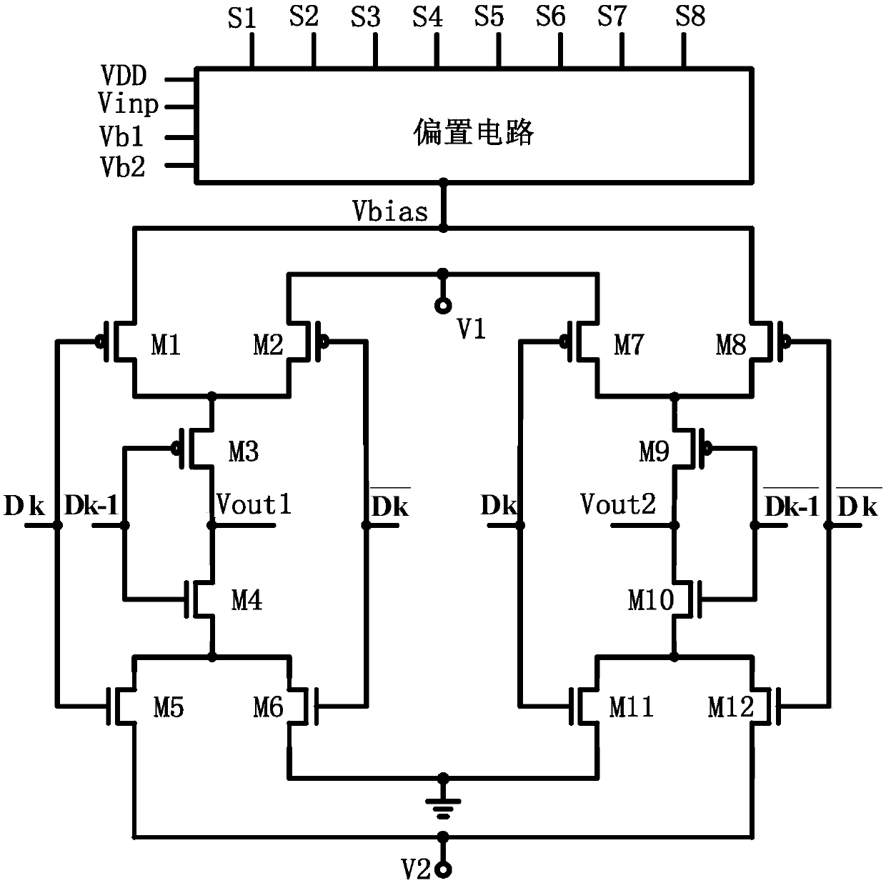
[0018] Embodiment one: if figure 1 As shown, a pre-emphasis driving circuit based on a cascode pseudo-differential structure includes a bias circuit, a first MOS transistor M1, a second MOS transistor M2, a third MOS transistor M3, a fourth MOS transistor M4, and a fifth MOS transistor M4. MOS tube M5, sixth MOS tube M6, seventh MOS tube M7, eighth MOS tube M8, ninth MOS tube M9, tenth MOS tube M10, eleventh MOS tube M11 and twelfth MOS tube M12, the first The MOS tube M1, the second MOS tube M2, the third MOS tube M3, the seventh MOS tube M7, the eighth MOS tube M8 and the ninth MOS tube M9 are all P-type MOS tubes, the fourth MOS tube M4, the fifth MOS tube M5, the sixth MOS tube M6, the tenth MOS tube M10, the eleventh MOS tube M11 and the twelfth MOS tube M12 are all N-type MOS tubes; the bias circuit has a power supply terminal, an input terminal, and a first bias voltage terminal , the second bias voltage terminal, the first voltage control terminal, the second voltage ...

Embodiment 2

[0019] Embodiment two: if figure 1 As shown, a pre-emphasis driving circuit based on a cascode pseudo-differential structure includes a bias circuit, a first MOS transistor M1, a second MOS transistor M2, a third MOS transistor M3, a fourth MOS transistor M4, and a fifth MOS transistor M4. MOS tube M5, sixth MOS tube M6, seventh MOS tube M7, eighth MOS tube M8, ninth MOS tube M9, tenth MOS tube M10, eleventh MOS tube M11 and twelfth MOS tube M12, the first The MOS tube M1, the second MOS tube M2, the third MOS tube M3, the seventh MOS tube M7, the eighth MOS tube M8 and the ninth MOS tube M9 are all P-type MOS tubes, the fourth MOS tube M4, the fifth MOS tube M5, the sixth MOS tube M6, the tenth MOS tube M10, the eleventh MOS tube M11 and the twelfth MOS tube M12 are all N-type MOS tubes; the bias circuit has a power supply terminal, an input terminal, and a first bias voltage terminal , the second bias voltage terminal, the first voltage control terminal, the second voltage ...

Embodiment 3

[0021] Embodiment three: as figure 1 As shown, a pre-emphasis driving circuit based on a cascode pseudo-differential structure includes a bias circuit, a first MOS transistor M1, a second MOS transistor M2, a third MOS transistor M3, a fourth MOS transistor M4, and a fifth MOS transistor M4. MOS tube M5, sixth MOS tube M6, seventh MOS tube M7, eighth MOS tube M8, ninth MOS tube M9, tenth MOS tube M10, eleventh MOS tube M11 and twelfth MOS tube M12, the first The MOS tube M1, the second MOS tube M2, the third MOS tube M3, the seventh MOS tube M7, the eighth MOS tube M8 and the ninth MOS tube M9 are all P-type MOS tubes, the fourth MOS tube M4, the fifth MOS tube M5, the sixth MOS tube M6, the tenth MOS tube M10, the eleventh MOS tube M11 and the twelfth MOS tube M12 are all N-type MOS tubes; the bias circuit has a power supply terminal, an input terminal, and a first bias voltage terminal , the second bias voltage terminal, the first voltage control terminal, the second voltag...


PUM


Abstract

The invention discloses a pre-emphasis drive circuit based on a cascade pseudo-differential structure. The drive circuit comprises a biasing circuit, a first MOS transistor, a second MOS transistor, athird MOS transistor, a fourth MOS transistor, a fifth MOS transistor, a sixth MOS transistor, a seventh MOS transistor, an eighth MOS transistor, a ninth MOS transistor, a tenth MOS transistor, an eleventh MOS transistor and a twelfth MOS transistor, wherein all the first MOS transistor, the second MOS transistor, the third MOS transistor, the seventh MOS transistor, the eighth MOS transistor and the ninth MOS transistor are P-type MOS transistors; all the fourth MOS transistor, the fifth MOS transistor, the sixth MOS transistor, the tenth MOS transistor, the eleventh MOS transistor and thetwelfth MOS transistor are N-type MOS transistors. The drive circuit provided by the invention has the advantages that output flexibility is high on the basis of a simple circuit structure, differentpre-emphasis voltage drive signals can be output as needed, and different environment requirements are met.

Description

technical field [0001] The invention relates to a pre-emphasis driving circuit, in particular to a pre-emphasis driving circuit based on a cascode pseudo-differential structure. Background technique [0002] With the continuous improvement of network and communication data transmission rates, people's demand for bandwidth is increasing. However, traditional electrical interconnection has serious disadvantages such as dielectric loss and channel attenuation. Therefore, the improvement of the bandwidth is greatly limited. [0003] Optical interconnection uses light waves as a transmission method to transmit information carriers, and performs parallel transmission and processing of optical information. Optical interconnection technology has incomparable advantages in high-speed data transmission environment - small crosstalk, high density, fast speed, low power consumption, etc., and will gradually replace traditional electrical interconnection. Among them, photonic devices t...

Claims


Application Information

Patent Timeline
Patent Type & Authority Applications(China)
IPC IPC(8): H03K19/0185
CPCH03K19/018507
Inventor 陈伟伟汪鹏君张亚伟李文辉杨建义
Owner NINGBO UNIV
Why Eureka
Try Eureka