Optical module and its control circuit and method

A technology of control circuit and optical module, applied in the field of optical communication

Active Publication Date: 2019-02-22
GUANGXUN SCI & TECH WUHAN +1
View PDF4 Cites 0 Cited by
  • Summary
  • Abstract
  • Description
  • Claims
  • Application Information

AI Technical Summary

Problems solved by technology

[0004] With the upgrading of optical module performance and the promotion of applications, the original memory map structure can no longer meet the needs, so the SFF-8472 standard upgrades the memory map structure and introduces the concept of extended table (also called extended page)

Method used


Image

  • Optical module and its control circuit and method
  • Optical module and its control circuit and method
  • Optical module and its control circuit and method

Examples


Embodiment Construction

[0025] Exemplary embodiments of the present invention will be described below with reference to the accompanying drawings.

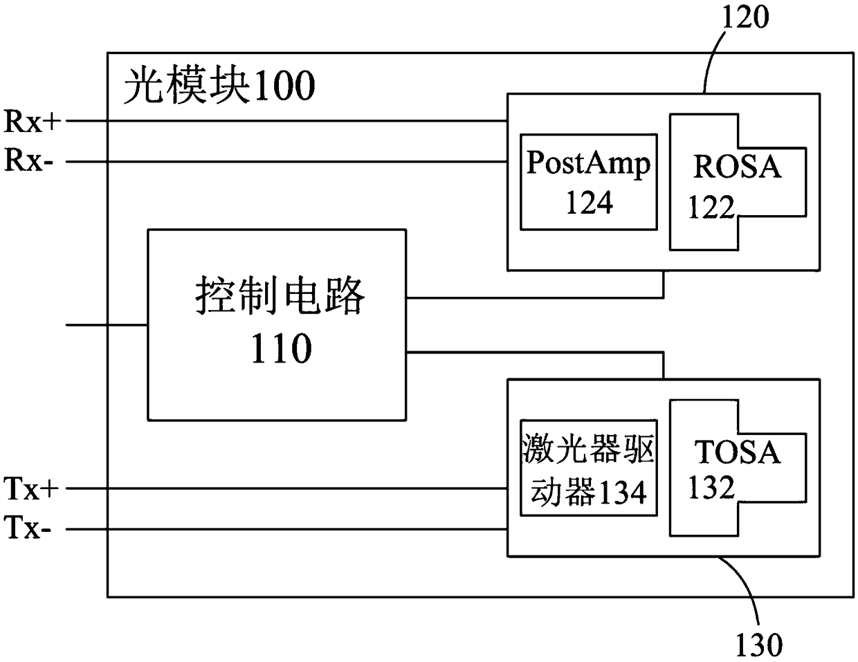
[0026] figure 1 A structural block diagram of an optical module 100 according to an embodiment of the present invention is shown. Such as figure 1 As shown, the optical module 100 may include a light receiving unit 120 , a light emitting unit 130 , and a control circuit 110 for controlling the light receiving unit 120 and the light emitting unit 130 .

[0027] The optical receiving unit 120 is used to receive an optical signal from an input optical fiber (not shown), convert it into an electrical signal, and after processing (eg, amplifying), provide the electrical signal to the host on the Rx+ and Rx- pins (not shown). Such as figure 1 As shown, the light receiving unit 120 may include a light receiving subassembly (ROSA) 122 and a post amplifier (PostAmp) circuit 124 . ROSA 122 may include a mechanical fiber optic receptacle for receiving an optic...


PUM


Abstract

The present invention relates to an optical module and its control circuit and method. An embodiment provides a control circuit for an optical module, the optical module includes a light receiving unit and a light emitting unit, the control circuit includes: a first memory for storing in a predefined location of the first memory a plurality of configuration parameters of the optical module; a second memory for storing a plurality of variables at a dynamically allocated location of the second memory, the plurality of variables including variables corresponding to the current operating state of the optical module and an analog-to-digital converter configured to receive an analog signal corresponding to the current operating state of the optical module, and convert the analog signal into a digital value, which is stored as a variable corresponding to the current operating state of the optical module in in the dynamically allocated location of the second memory.

Description

technical field [0001] The present invention generally relates to the field of optical communication, and more particularly, relates to an optical module with a digital diagnostic monitoring (DDM) function and a control circuit and method for the optical module. Background technique [0002] An optical module is a core component of a modern optical communication system, and generally includes an optical receiving module, an optical transmitting module, an optical transceiver module, and an optical forwarding module. As a typical example of an optical module, an optical transceiver module, also called an optical transceiver (optical transceiver), generally includes an optical transmitting unit, an optical receiving unit, and a control circuit. With the development of optical communication technology, optical modules generally have a digital diagnostic monitoring function (DDM: Digital Diagnostic Monitoring), so that the system can query and monitor the working status of the o...

Claims


Application Information

Patent Timeline
Patent Type & Authority Patents(China)
IPC IPC(8): H04B10/40
CPCH04B10/40G06F12/1081G06F2212/656H04B10/07955H04B10/0799H04B10/07H04B10/806G06F3/0622G06F3/0659G06F13/4282G06F2213/0016H04B10/03H04B10/0797H04B10/43
Inventor 陈龙高繁荣张军余向红
Owner GUANGXUN SCI & TECH WUHAN
Why Eureka
Try Eureka