
Array substrate

An array substrate and glass substrate technology, applied in the display field, can solve problems such as limited bonding strength, and achieve the effect of improving surface wear resistance and simple process

Inactive Publication Date: 2018-02-06
HEFEI HUIKE JINYANG TECH
View PDF3 Cites 1 Cited by
  • Summary
  • Abstract
  • Description
  • Claims
  • Application Information

AI Technical Summary

Problems solved by technology

[0003] The purpose of the present invention is to provide an array substrate, which solves the problem of limited bonding strength in the existing array substrates where the sealant is coated on the surface of the array substrate

Method used


Image

  • Array substrate
  • Array substrate

Examples


Embodiment 1

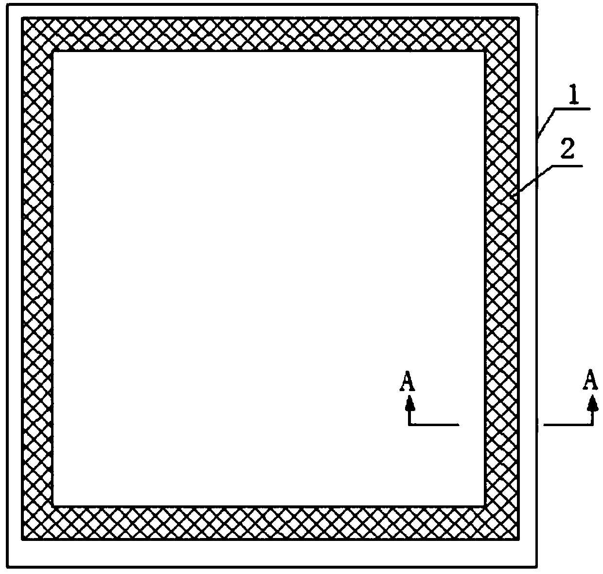
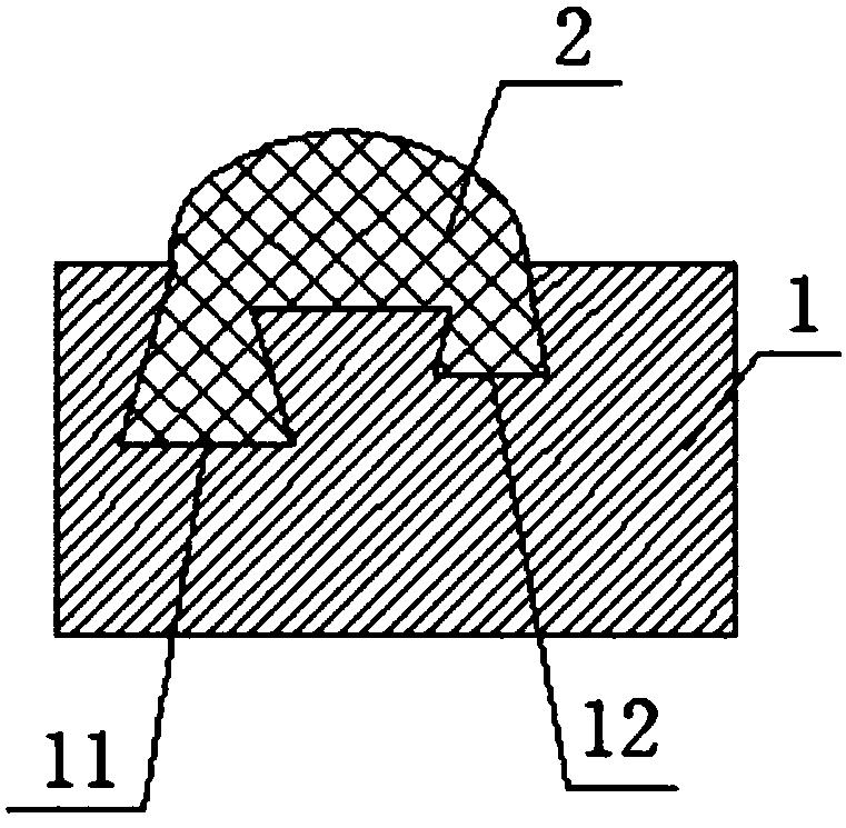
[0029] See Figure 1 to Figure 2 , The present invention provides an array substrate, including: a glass substrate 1 and a sealant 2 coated on the glass substrate 1; the glass substrate 1 is provided with a first frame-shaped groove body 11 and a second frame-shaped groove Body 12; The first frame-shaped tank body 11 is located inside the second frame-shaped tank body 12; the cross-sections of the first frame-shaped tank body 11 and the second frame-shaped tank body 12 are trapezoidal, The trapezoidal lower bottoms of the first frame-shaped tank body 11 and the second frame-shaped tank body 12 are located below, and a connecting portion is provided above the upper bottom area. The first frame-shaped tank body 11 and the second frame The upper part of the shaped tank body 12 is communicated through the connecting portion; the sealant 2 is coated on the glass substrate 1, and the sealant 2 is filled in the first frame-shaped tank body 11 and the second frame-shaped tank The insi...

Embodiment 2

[0032] A method for manufacturing a glass substrate of an array substrate, the steps are as follows:

[0033] 1), structure and separate processing

[0034] The glass substrate is provided with a first frame-shaped tank body and a second frame-shaped tank body; the first frame-shaped tank body is located inside the second frame-shaped tank body; the cross section of the first frame-shaped tank body and the second frame-shaped tank body Both are trapezoidal, the trapezoidal bottoms of the first frame-shaped tank body and the second frame-shaped tank body are located below, and the sealant is filled in the first frame-shaped tank body, the second frame-shaped tank body and the inside of the communicating part;

[0035] The glass substrate is made by the float glass manufacturing process; the frame-shaped tank is formed by cutting ruby;

[0036] 2), pre-treatment

[0037] Soak the cut glass substrate in the bath for at least 5 minutes, take it out and rinse it immediately, and then dry it...


PUM


Abstract

The invention relates to the technical field of display, in particular to an array substrate. The array substrate comprises a glass substrate and frame glues applied onto the glass substrate, whereina first frame-shaped groove body and a second frame-shaped groove body are arranged on the glass substrate, the first frame-shaped groove body is arranged in the inner side of the second frame-shapedgroove body. The cross section of the first frame-shaped groove body and the second frame-shaped groove body are trapezoidal. The trapezoidal lower bottom of the first frame-shaped groove body and thesecond frame-shaped groove body are located on the lower part. A communication part is arranged above the upper bottom region. The upper part of the first frame-shaped groove body and the second frame-shaped groove body are communicated with each other through the communication part. The frame glues are applied onto the glass substrate and filled in the first frame-shaped groove body and the second frame-shaped groove body and the interior of the communication part. The setting of the trapezoidal first frame-shaped groove body and the second frame-shaped groove body increases the contact areaof the frame glues and the glass substrate, and enhances the bonding strength between the frame glues and the glass substrate.

Description

Technical field [0001] The present invention relates to the field of display technology, and in particular to an array substrate. Background technique [0002] The liquid crystal display is a flat and ultra-thin display device, which consists of a certain number of color or black and white pixels, and is placed in front of a light source or reflection. Liquid crystal displays have very low power consumption, so they are favored by engineers and are suitable for electronic devices that use batteries. Its main principle is to stimulate the liquid crystal molecules to generate dots, lines, and surfaces with the back light tube to form a picture. The existing liquid crystal panel usually includes an upper substrate and a lower substrate bonded by a sealant. In the existing array substrate, the sealant is coated on the surface of the array substrate, and the bonding strength is limited. Summary of the invention [0003] The object of the present invention is to provide an array subst...

Claims


Application Information

Patent Timeline
Patent Type & Authority Applications(China)
IPC IPC(8): G02F1/1339C03C21/00C03C23/00
CPCG02F1/1339C03C21/001C03C23/007
Inventor 白航空
Owner HEFEI HUIKE JINYANG TECH
Learn More