Intervertebral fusion machine with bone ingrowth millipores for cervical vertebra

An intervertebral fusion device and ingrowth technology, which is applied in the field of intervertebral fusion devices, can solve problems such as insufficient support force of the support surface of the fusion device, instability of the cervical vertebral body, fracture of intervertebral fusion bones, etc.

Pending Publication Date: 2018-02-09
TIANJIN ZHENGTIAN MEDICAL INSTR CO LTD
View PDF5 Cites 3 Cited by
  • Summary
  • Abstract
  • Description
  • Claims
  • Application Information

AI Technical Summary

Problems solved by technology

[0004] The purpose of the present invention is to overcome the problem existing in the prior art that under the effect of vertebral body growth, the bone in the bone grafting window area grows too fast, and it is easy to suspend the upper and lower support surfaces of the fusion device, resulting in insufficient support force on the support surface of the fusion device and load-bearing transfer. With the physiological activities of the human body, the fusion bone in the area of ​​the only bone graft window will increase, resulting in fractures of intervertebral fusion bones and instability of the cervical vertebral body. Its purpose is to provide a cervical intervertebral fusion device with bone ingrowth microholes

Method used


Image

  • Intervertebral fusion machine with bone ingrowth millipores for cervical vertebra
  • Intervertebral fusion machine with bone ingrowth millipores for cervical vertebra
  • Intervertebral fusion machine with bone ingrowth millipores for cervical vertebra

Examples


Embodiment Construction

[0025] The cervical intervertebral fusion device with bone ingrowth microholes of the present invention will be described in detail below in conjunction with the accompanying drawings and examples:

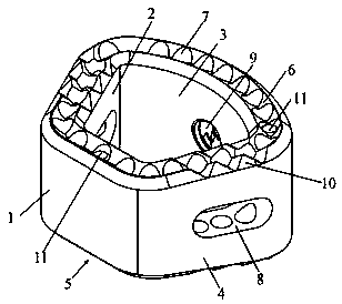
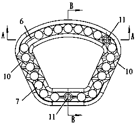
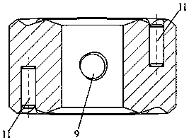
[0026] Such as Figure 1~4 As shown, a cervical vertebral intervertebral fusion device with bone ingrowth microholes includes a fan-shaped cross-section formed by connecting the front wall 1, the left wall 2, the back wall 3 and the right wall 4 sequentially. The body 5 of the tetrahedral structure forms a bone graft window in the hollow space surrounded by it; the upper end of the body 5 forms a circle of trapezoidal grooves 6 that are wide at the top and narrow at the bottom, and the bottom of the groove 6 forms a plurality of vertical bone ingrowth The microhole 7 forms a positioning hole 8 on the left wall 2 and the rear wall 3, and forms a threaded hole 9 in the middle of the rear wall 3;

[0027] The edges of the upper and lower end faces of the left wall 2 and the rear wal...


PUM


Abstract

The invention discloses an intervertebral fusion machine with bone ingrowth millipores for cervical vertebra. The fusion machine comprises a machine body of which the cross section is in a sector shape, wherein the machine body is defined in the mode that a front machine wall, a left machine wall, a back machine wall and a right machine wall are connected in sequence and is of a tetrahedron structure; a circle of a trapezoid groove with a wide upper portion and a narrow lower portion is formed in the upper end surface of the machine body, a plurality of vertically arranged bone ingrowth millipores are formed in the groove bottom of the groove, and threaded holes are formed in the middle of the back machine wall; developing needles are arranged on the junction portion of the left machine wall and the back machine wall and the junction portion of the back machine wall and the right machine wall and arranged in the machine wall of the center line of the front machine wall. According to the intervertebral fusion machine, a polyetheretherketone material is used, a bone grafting window and the developing needles are designed, the millipores for bone ingrowth are added, and the developingneedles are used for displaying the implantation position of the fusion machine under the X-ray; artificial bones of which the diameters are identical to the diameters of the millipores are implantedinto the bone ingrowth millipores for inducing bone ingrowth, bone fusion on a supporting surface can be improved, the area of intervertebral fusion is effectively increased, and the stability effectof the vertebral body of intervertebral fusion after the operation is improved.

Description

technical field [0001] The invention belongs to an intervertebral fusion device, in particular to a cervical intervertebral fusion device with bone ingrowth microholes. Background technique [0002] Cervical disc herniation is one of the common diseases in spine surgery. The effective way to treat cervical disc herniation is to perform intervertebral fusion surgery, that is, to remove the diseased intervertebral disc, and then place a cervical vertebra in the same shape as the intervertebral disc at the removed intervertebral disc. The fusion device can achieve immediate stabilization of the cervical spine, promote fusion, rebuild and maintain the intervertebral height and the physiological curvature of the cervical spine. [0003] At present, ordinary cervical fusion cages do not have micro-holes on the supporting surface, so the area of ​​bony fusion on the coronal surface of the cervical vertebral body is small, and there are only fusion areas at the upper and lower ends ...

Claims


Application Information

Patent Timeline
Patent Type & Authority Applications(China)
IPC IPC(8): A61F2/44A61L27/18A61L27/50
CPCA61L27/18A61L27/50A61F2/30771A61F2/4455A61F2002/3008A61F2002/30772A61L2430/38C08L61/16A61F2002/30593
Inventor 袁森
Owner TIANJIN ZHENGTIAN MEDICAL INSTR CO LTD
Why Eureka
Try Eureka