
Three-cavity cervix balloon dilatation device

A dilator and balloon technology, used in dilators, balloon catheters, drug devices, etc., can solve the problems of inconspicuous cervical score, failure to induce labor, poor dilation effect, etc., to shorten maturation time, improve strength, The effect of promoting the progress of labor

Pending Publication Date: 2018-02-09
孙利华
View PDF0 Cites 8 Cited by
  • Summary
  • Abstract
  • Description
  • Claims
  • Application Information

AI Technical Summary

Problems solved by technology

[0005] Analysis of the reasons for the poor effect of single and double balloons on pregnant women with low cervical score: the cervical canal of adult women is about 3cm long, mainly composed of connective tissue, and also contains smooth muscle fibers, blood vessels and elastic fibers, blood vessels and elastic fibers, The process of vaginal delivery is accompanied by the shortening and softening of the cervical canal, and then the expansion process. The cervical balloon acts on the internal orifice of the cervix and the external os of the cervix, and achieves mechanical stimulation by continuously compressing the upper and lower ends of the cervix. However, for the cervical For immature pregnant women, or the scars formed by the cervix once treated (physiotherapy, LEEP), the force directly acting on the cervix is ​​invariable, and the expansion effect is poor. If the use time is not extended ( Prolonged use time can increase the chance of intrauterine infection) The improvement of cervical score is not obvious, leading to the failure of induced labor later

Method used


Image

  • Three-cavity cervix balloon dilatation device

Examples


Embodiment Construction

[0017] The present invention will be described in detail below in conjunction with the implementations shown in the drawings, but it should be noted that these implementations are not limitations of the present invention, and those of ordinary skill in the art based on the functions, methods, or structural changes made by these implementations Equivalent transformations or substitutions all fall within the protection scope of the present invention.

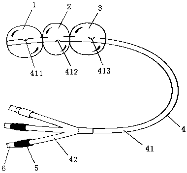
[0018] see figure 1 , is the structure diagram of the three-chamber cervical balloon dilator proposed by the present invention.

[0019] Such as figure 1 As shown, the three-chamber cervical balloon dilator includes: a balloon group, a rubber tube 4, and an injection port 5; the first end of the rubber tube 4 is connected to the injection port 5, and the second end of the rubber tube 4 is provided with a balloon group, The balloon group consists of a first balloon 1, a second balloon 2 and a third balloon 3 arranged in sequence ...


PUM


Abstract

The invention discloses a three-cavity cervix balloon dilatation device. The three-cavity cervix balloon dilatation device comprises a balloon set, a rubber tube, injection ports and plugs; a first end of the rubber tube is connected with the injection ports, the balloon set is arranged at a second end of the rubber tube, and a first balloon, a second balloon and a third balloon of the balloon setare arranged at the second end of the rubber tube in sequence; the rubber tube is composed of a protective outer tube and injection inner tubes, a first fixing opening, a second fixing opening and athird fixing opening are formed in the positions, located at the first balloon, the second balloon and the third balloon, of the rubber tube respectively, wherein the first fixing opening, the secondfixing opening and the third fixing opening are connected with one ends of the three injection inner tubes respectively, the other ends of the three injection inner tubes penetrate the protective outer tube and are fixedly connected with the injection ports, and needle cores are arranged on the injection ports. According to the three-cavity cervix balloon dilatation device, the capacity of cervical dilatation can be greater improved, and the device has high use value for labor induction of a full-term pregnant woman with an extremely low cervical score or labor induction of intermediate stagepregnancy.

Description

technical field [0001] The invention relates to the technical field of obstetrics and gynecology medical devices, in particular to a three-chamber cervical balloon dilator. Background technique [0002] Cervical dilation balloon is a non-drug midwifery device, which can safely, naturally, and gradually dilate the cervix, and increase the success rate of labor induction. The sac continuously compresses and dilates the cervix, making it soft and shortened. The balloon in the uterine cavity can expand the uterine cavity, promote the release of oxytocin from the posterior pituitary gland, and induce uterine contractions; The endogenous prostaglandins in the cervix are synthesized and released, causing uterine contractions and promoting the softening and maturation of the cervix. Ripening and dilating the cervix is ​​accomplished by the balloon providing a gentle, long-lasting dilating force at the internal and external os of the cervix, with obvious advantages. [0003] Curre...

Claims


Application Information

Patent Timeline
IPC IPC(8): A61M29/04A61B17/42A61B17/12A61M25/10
CPCA61M25/1011A61M29/02A61B17/1204A61B17/12099A61B17/12136A61B17/42A61B2017/4225A61M2210/1433A61M2025/1013A61M2210/005
Inventor 孙利华
Owner 孙利华
Learn More