Supercharge Your Innovation With Domain-Expert AI Agents!

Continuous cutting medical test tube equipment

A test tube and equipment technology, applied in the field of continuous cutting medical test tube equipment, can solve problems such as low work efficiency, difficult to cut end faces, uneven test tube port sections, etc., and achieve the effect of improving the cutting effect

Inactive Publication Date: 2019-05-24
武永信 +1
View PDF5 Cites 0 Cited by
  • Summary
  • Abstract
  • Description
  • Claims
  • Application Information

AI Technical Summary

Problems solved by technology

The conventional cutting method is to slide an arc on the outer wall of the test tube with a glass knife, that is, draw a circle on the outer wall of the test tube, and then tap the outer wall of the test tube with a glass knife in an area far away from the arc to obtain the desired glass tube. ; The section of the test tube port obtained by this method is prone to unevenness, which is due to the fact that the circular arc is not closed when the glass knife slides the circular arc on the peripheral wall of the test tube, that is to say, the starting point of the circular arc is the same as The termination point is not docked, and it is impossible to ensure that the plane formed by the arc is perpendicular to the axis of the test tube. In a word, it is difficult to obtain a flat cutting end surface through the operating device and operating method of the prior art; in addition, after drawing the arc Afterwards, the operator is required to knock the test tube manually. Once the operator uses a large or small force, it is difficult to obtain a qualified test tube at one time. That is to say, the working efficiency of obtaining the test tube by the knocking method of the prior art is too low

Method used


Image

  • Continuous cutting medical test tube equipment
  • Continuous cutting medical test tube equipment
  • Continuous cutting medical test tube equipment

Examples


Embodiment Construction

[0023] The present invention will be further described below in conjunction with the accompanying drawings and specific embodiments.

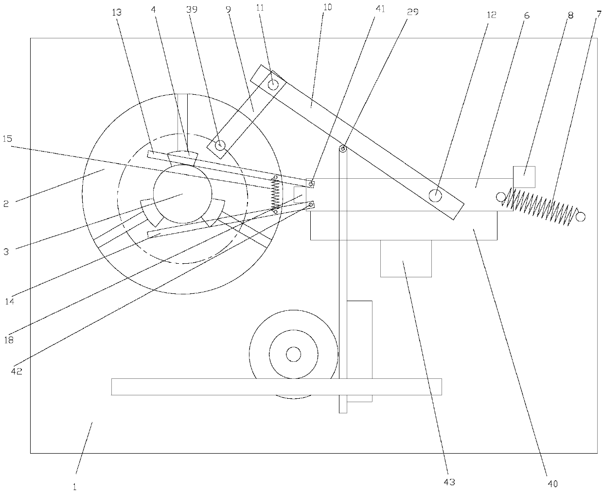
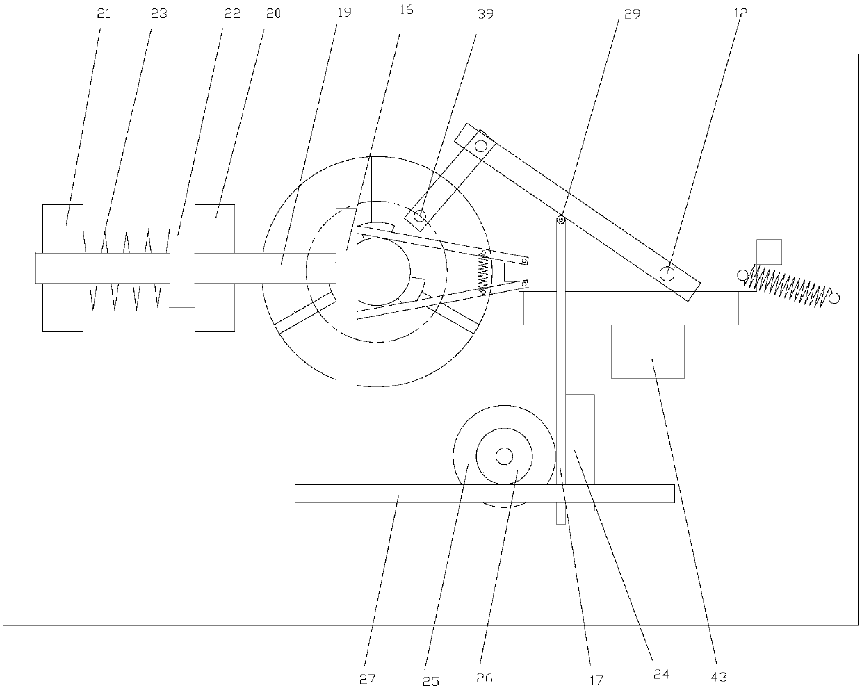
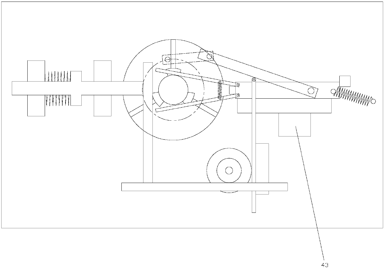
[0024]As shown in the figure, the continuous cutting medical test tube equipment of the present invention includes a base 1, the base 1 is rotatably connected with a disc 2 through a power device, and the disc 2 is provided with a three-jaw chuck 4 for locking the test tube 3, The disc 2 is provided with a through hole 5 for the test tube 3 to pass through; the disc 2 is rotatably connected with a first connecting rod 9, the first connecting rod 9 is eccentrically connected to the disc 2, and the first connecting rod 9 passes through the transmission rod 11 is rotatably connected with a second connecting rod 10, and the transmission rod 11 is arranged along the axis direction of the disk 2. Through the setting of the transmission rod 11, the first connecting rod 9 and the second connecting rod 10 can be arranged at a certain distance, that is, t...


PUM


Abstract

The invention discloses continuous cutting equipment for medical test tubes. The continuous cutting equipment comprises a base (1); a disc (2) is rotationally connected to the base (1) through a powerdevice and provided with a three-claw chuck (4); a first connection rod (9) is rotationally connected to the disc (2), and a second connection rod (10) is rotationally connected to the first connection rod (9) through a transmission rod (11); a sliding table (6) is slidably connected to the base (1) through a guide block (40), the guide block (40) is slidably connected to the base (1) in the axisdirection of the disc (2), and the sliding table (6) is rotationally connected with the second connection rod (10) through a first hinged point (12); and the base (1) is provided with a lock block (8). Through the continuous cutting equipment for the medical test tubes, more manpower cost can be reduced, the production efficiency and machining efficiency can be improved through more automatic mechanical transmission, and the continuous cutting equipment which can cut out flat end faces and is higher in working efficiency is provided.

Description

technical field [0001] The invention relates to the field of medical equipment and biochemical experiment equipment, in particular to a continuous cutting medical test tube equipment. Background technique [0002] In medical laboratories, it is often necessary to use test tubes made of glass to contain various liquids, and glass tubes are fragile, especially during the process of cutting glass tubes. In the production and processing process of some test tube manufacturers, a long test tube is mostly cut in sections to obtain test tubes of various lengths suitable for test occasions. The conventional cutting method is to slide a circular arc with a glass knife on the outer wall of the test tube, that is, draw a circle on the outer wall of the test tube, and then tap the outer wall of the test tube with a glass knife in an area far away from the arc to obtain the required glass tube. ; The section of the test tube port obtained by this method is prone to unevenness, which is ...

Claims


Application Information

Patent Timeline
Patent Type & Authority Patents(China)
IPC IPC(8): C03B33/06B28D5/00
CPCB28D5/00B28D7/04
Inventor 武永信周素芹刘春风徐姗姗
Owner 武永信
Features
  • R&D
  • Intellectual Property
  • Life Sciences
  • Materials
  • Tech Scout
  • Unparalleled Data Quality
  • Higher Quality Content
  • 60% Fewer Hallucinations
Learn More