
High-efficiency wallpaper printing production device with high printing quality

A technology of printing quality and production equipment, which is applied in the field of high-efficiency wallpaper printing production equipment, can solve the problems of complex structure and high cost of shaftless printing plate loading equipment, and achieve the effect of simple structure, low cost and less use of electrical components

Inactive Publication Date: 2018-02-09
湖北巴萨装饰材料股份有限公司
View PDF0 Cites 1 Cited by
  • Summary
  • Abstract
  • Description
  • Claims
  • Application Information

AI Technical Summary

Problems solved by technology

[0002] Wallpaper, also known as wallpaper, is a widely used interior decoration material, because wallpaper has various colors, rich patterns, luxurious style, safety and environmental protection, convenient construction, affordable price and many other characteristics that cannot be compared with other interior decoration materials. Therefore, it has been popularized to a considerable extent in developed countries and regions such as Europe, America, and Japan. Wallpapers are divided into many categories, such as coated wallpapers, coated wallpapers, embossed wallpapers, etc. Usually, bleached chemical wood pulp is used to produce base paper, and then processed through different processes. processing, such as coating, printing, embossing or surface coating, and finally cut and packaged before leaving the factory. Because of its certain strength, toughness, beautiful appearance and good water resistance, it is widely used in residential buildings, Indoor decoration of offices, hotels, hotels, etc., the current shaftless printing plate loading device has a complex structure, too many electrical applications, and is expensive

Method used


Image

  • High-efficiency wallpaper printing production device with high printing quality
  • High-efficiency wallpaper printing production device with high printing quality
  • High-efficiency wallpaper printing production device with high printing quality

Examples


Embodiment Construction

[0016] The technical solutions in the embodiments of the present invention will be clearly and completely described below in conjunction with the accompanying drawings in the embodiments of the present invention. Obviously, the described embodiments are only a part of the embodiments of the present invention, rather than all the embodiments.

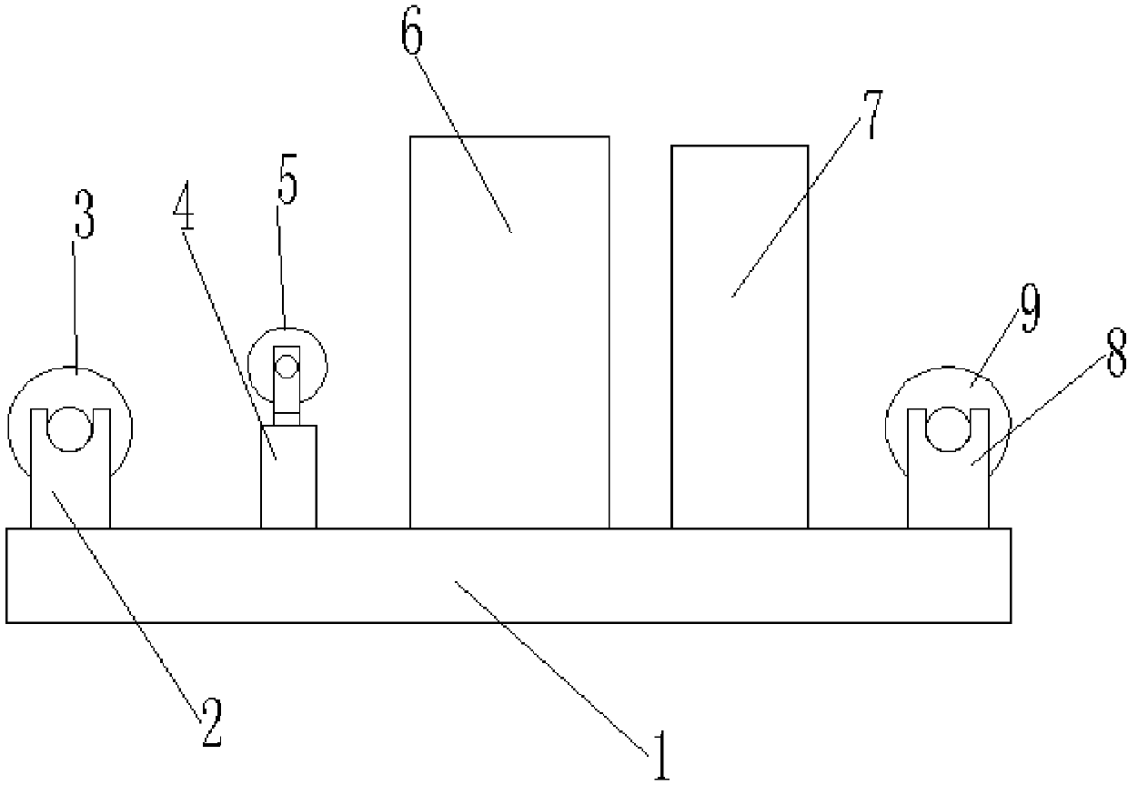
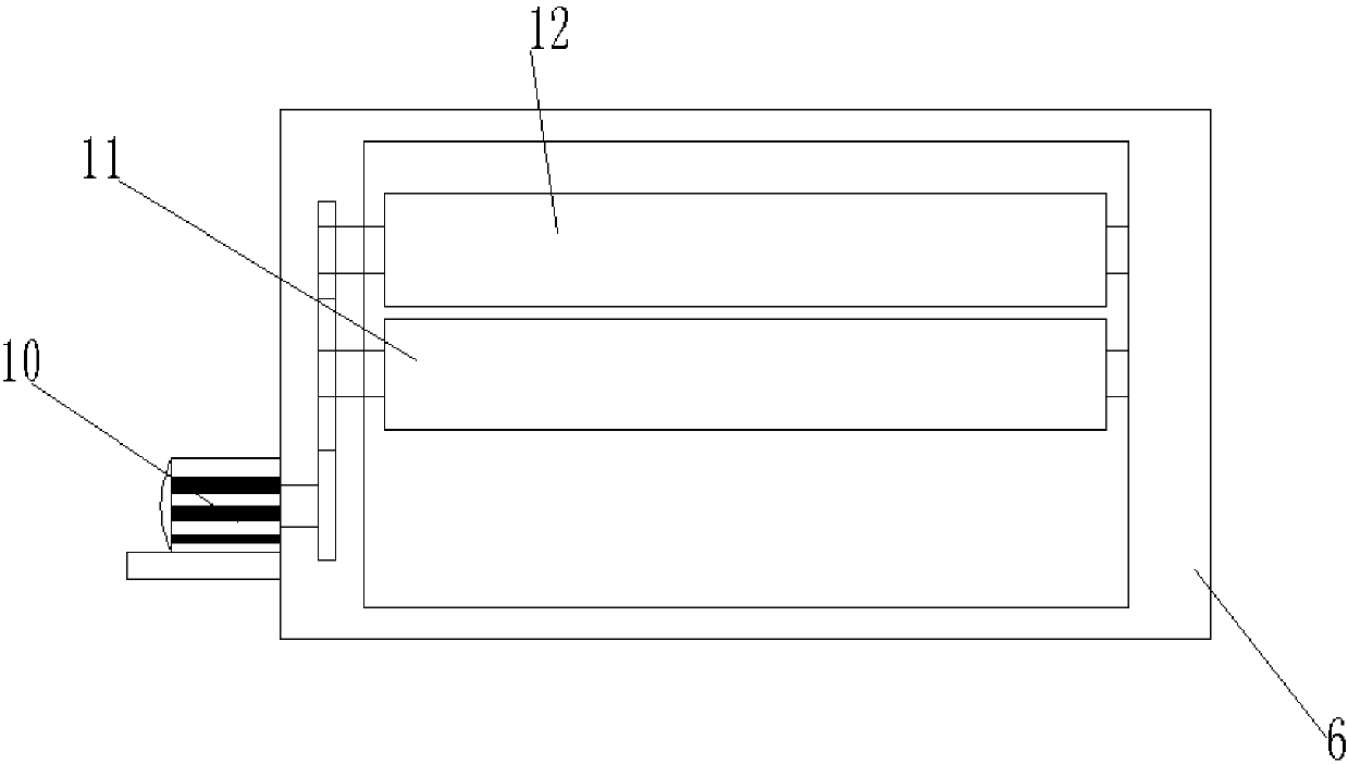
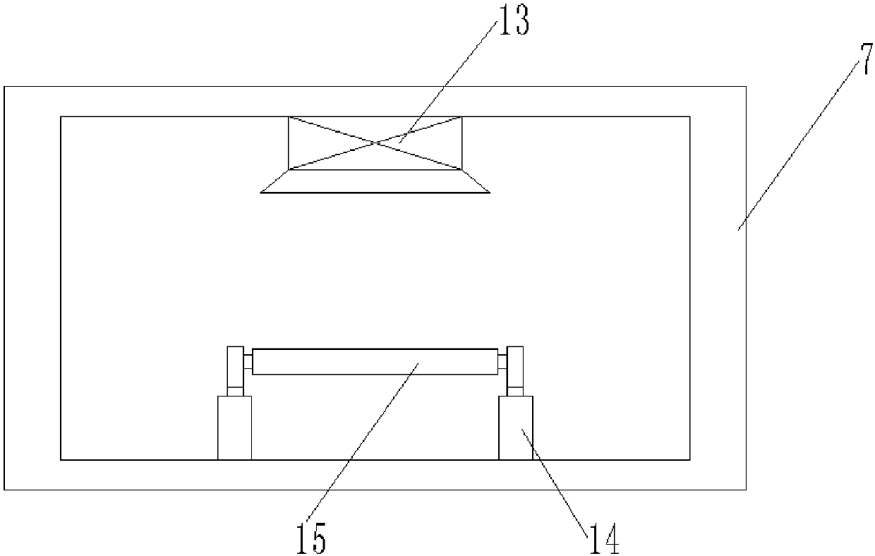
[0017] Reference Figure 1-3 , A high-efficiency wallpaper printing production device with high printing quality, comprising a worktable 1, a first U-shaped support frame 2 is welded on both sides of the outer wall on the top side of the worktable 1, and two first U-shaped support frames 2 The openings are provided with the same input roller 3, the two ends of the input roller 3 are respectively placed on the inner wall of the opening of the two first U-shaped support frames 2, and both sides of the outer wall of the top end of the worktable 1 are fixed with the first cylinder 4 by screws , The top outer wall of the worktable 1 is fixed wit...


PUM


Abstract

The invention discloses a high-efficiency wallpaper printing production device with high printing quality, which includes a workbench, a first U-shaped support frame is welded on both sides of the outer wall on one side of the top end of the workbench, and the openings of the two first U-shaped support frames The same input roller is provided at each place, and the two ends of the input roller are respectively placed on the opening inner walls of the two first U-shaped support frames, and the first cylinder is fixed on both sides of the outer wall at the top of the workbench by screws. The printing box is fixed on the outer wall of the top of the table by screws, and the first air cylinders are located between the printing box and the first U-shaped support frame. The invention has simple structure, less use of electrical components, lower cost, and the use of the dryer can dry the printed wallpaper in time, avoiding self-pollution during collection and affecting the printing quality, and the first cylinder and the second cylinder cooperate in time Adjust the tension of the wallpaper to avoid looseness or breakage, improve the printing quality and save the cost.

Description

Technical field [0001] The invention relates to the technical field of wallpaper printing, in particular to a high-efficiency wallpaper printing production device with high printing quality. Background technique [0002] Wallpaper is also called wallpaper. It is a widely used interior decoration material, because it has various colors, rich patterns, luxurious style, safety and environmental protection, convenient construction, reasonable price and other characteristics that other interior decoration materials cannot match. Therefore, it has gained considerable popularity in developed countries and regions such as Europe, America and Japan. Wallpaper is divided into many categories, such as coated wallpaper, coated wallpaper, embossed wallpaper, etc. The base paper is usually produced with bleached chemical wood pulp, and then undergoes different processes. Processing, such as coating, printing, embossing or surface coating, and finally cut and packaged before leaving the factory...

Claims


Application Information

Patent Timeline
IPC IPC(8): B41F17/00B41F23/04
CPCB41F17/00B41F23/04
Inventor 李荣华
Owner 湖北巴萨装饰材料股份有限公司
Learn More