
Regulation storage tank containing water passing groove

A technology for storage tanks and water tanks, which is applied to waterway systems, water supply devices, drainage structures, etc., can solve the problems of unsuitable land occupation and buffer corridors occupying a large space, etc., to achieve a small footprint and relieve land use tension , keep clean effect

Inactive Publication Date: 2018-02-09
WUHAN SHENGYU DRAINING SYST
View PDF1 Cites 0 Cited by
  • Summary
  • Abstract
  • Description
  • Claims
  • Application Information

AI Technical Summary

Problems solved by technology

But the buffer corridor will take up a lot of space, so it is not suitable for some tight areas

Method used


Image

  • Regulation storage tank containing water passing groove
  • Regulation storage tank containing water passing groove

Examples


Embodiment 1

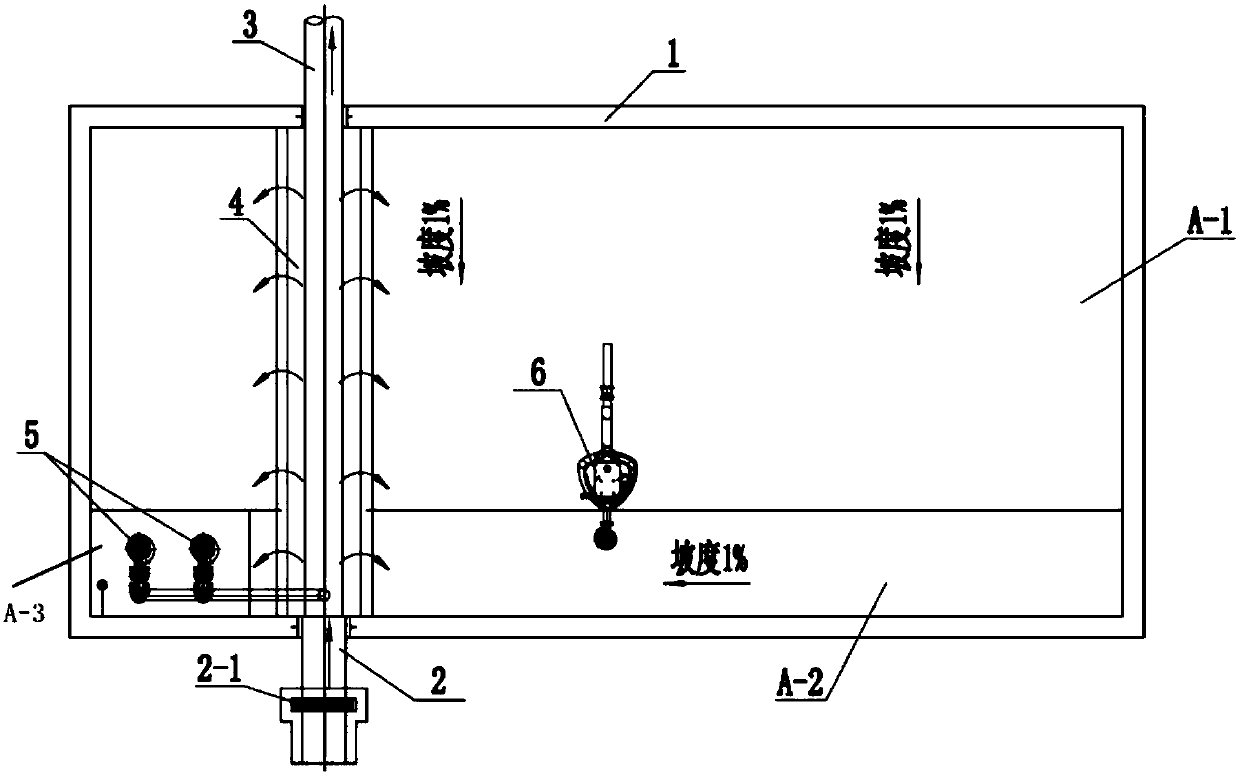
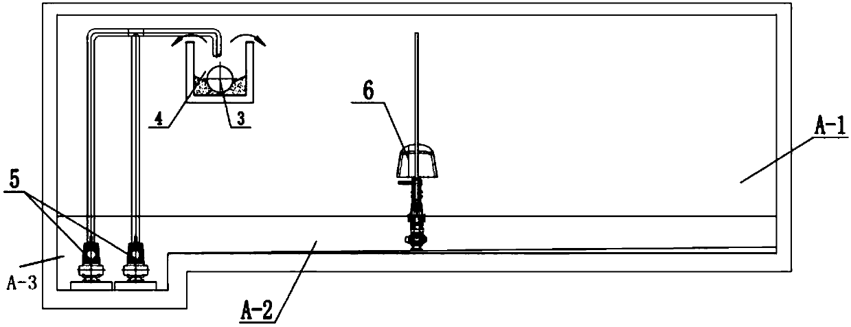
[0033] In the present embodiment, the structure of a primary rain storage tank 1 comprising a water tank 4 is as follows: figure 1 with figure 2 shown. The left, right, front and rear of the primary rain storage tank 1 are respectively the direction of the left side wall, the direction of the right side wall, the direction of the front side wall and the direction of the rear side wall. A water inlet pipe 2 is arranged on the front side wall, and a pipeline 3 leading to a sewage treatment plant is arranged on the rear side wall. The water inlet pipe 2 is provided with a bottom opening weir gate 2-1. On the top of the initial rain storage tank 1, a water tank 4 is set between the front and rear side walls, and the walls on both sides of the water tank 4 are higher than the highest water level H1 of the initial rain storage tank 1. One end of the water tank 4 is connected to the water inlet pipe 2, and the other end is connected to the pipeline 3 leading to the sewage treatme...


PUM


Abstract

The invention provides a storage tank comprising a water tank, the water tank is located on the upper part of the storage tank, the walls on both sides of the water tank are higher than the highest water level of the storage tank, and one end of the tank is connected to the inlet of the storage tank. The water pipes are connected, and one end is connected to the pipeline leading to the sewage treatment plant. The storage tank of the present invention adopts the overflow water inlet structure of the water tank, and the water inlet area occupies a small area, which can relieve the shortage of land in some areas. Moreover, the present invention also adopts a slope-shaped bottom structure, which can prevent large-area deposition of silt at the bottom of the storage tank. In addition, the present invention can also use washing equipment to stir and aerate the mixed sewage to be stored, and when the water level to be stored is low, the bottom of the pool can be washed to keep the bottom of the pool clean.

Description

technical field [0001] The invention belongs to the technical field of water supply and drainage, and in particular relates to a storage tank including a water tank. Background technique [0002] The storage tank is a device widely used in the field of water treatment, and its main purpose is to store sewage and initial rainwater. In the urban drainage network, the sewage treatment plants built in the early days could not meet the treatment needs of sewage and initial rainwater in the existing drainage network due to various reasons, so one or more storage tanks were often built in the network Ways to ease the treatment pressure of sewage treatment plants. [0003] When it rains, when the sum of the initial rainwater flow and sewage flow is greater than the maximum treatment capacity of the sewage treatment plant, part of the initial rainwater and sewage will enter the sewage treatment plant for treatment, and the remaining initial rainwater and sewage will be accumulated i...

Claims


Application Information

Patent Timeline
Patent Type & Authority Applications(China)
IPC IPC(8): E03F5/10E03F5/22E03F7/02E03F7/04E03F9/00
CPCE03F5/10E03F5/105E03F5/108E03F5/22E03F7/02E03F7/04E03F2201/10
Inventor 李浩
Owner WUHAN SHENGYU DRAINING SYST
Learn More