Phase change heat exchanger used for high-performance computer

A phase change heat exchanger, computer technology, applied in indirect heat exchangers, lighting and heating equipment, etc., can solve the problems of electronic components, endangering the safety of pump use, cavitation, etc., to achieve the effect of safe operation

Pending Publication Date: 2018-02-09
大冶斯瑞尔换热器有限公司
View PDF8 Cites 0 Cited by
  • Summary
  • Abstract
  • Description
  • Claims
  • Application Information

AI Technical Summary

Problems solved by technology

[0002] As the functions of high-performance computers become more and more powerful, the comprehensive power of electronic components is getting higher and higher, and the heat generated is also increasing. The traditional air cooling and cold plate can no longer meet the requirements of use, and more requirements are put forward for the heat exchanger. high requirements
In the high-performance computer, the electronic components are installed in the case and soaked in the liquid evaporation medium. When the high-performance computer is working, the electronic components generate a lot of heat, the liquid evaporation medium evaporates into a gaseous state, and the evaporated gaseous evaporation medium enters the condenser. After condensing, it enters the chassis again through the pump. Since the pump generates heat during operation, the liquid evaporation medium evaporates in the pump after absorbing heat, and the gaseous evaporation medium has cavitation on the pump impeller, which endangers the use of the pump. At the same time, the high-performance computer belongs to Commercial products have very strict requirements on the overall space size, and the independent condenser and subcooler design cannot meet the use requirements; in addition, once the condensed water in the condenser leaks, it will cause serious damage to the electronic components in the chassis. influences

Method used


Image

  • Phase change heat exchanger used for high-performance computer
  • Phase change heat exchanger used for high-performance computer
  • Phase change heat exchanger used for high-performance computer

Examples


Embodiment Construction

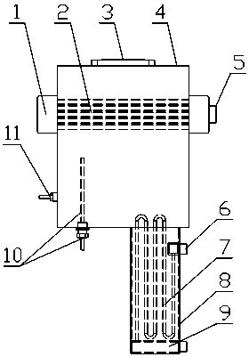
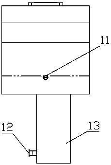
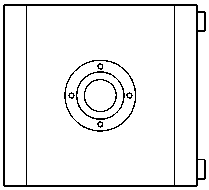
[0014] The present invention is a phase-change heat exchanger for high-performance computers, which has a condenser shell 4, and a strengthened condensation pipe 2 is arranged in the horizontal direction of the condenser shell, and a stream of water inlets are respectively arranged at the left and right ends of the strengthened condenser pipe End cover 5 and a water return end cover 1, the condenser shell above the enhanced condensation pipe is provided with a gaseous evaporation medium inlet 3, and a subcooler 13 is provided at the bottom of the condenser shell, and the subcooler has a supercooler. Cooler housing 8, the subcooler housing communicates with the inside of the condenser housing, and the inside of the subcooler housing is arranged with several U-shaped supercooled tubes 7 connected end to end, and the upper end of the U-shaped supercooled tube is arranged There are two water outlets 6 hidden in the subcooler housing wall, the lower end of the U-shaped supercooling ...


PUM


Abstract

The invention relates to a phase change heat exchanger used for a high-performance computer. The phase change heat exchanger is provided with a condenser shell, a condensation enhancement pipe is transversely arranged in the condenser shell, the left end and the right end of the condensation enhancement pipe are provided with a water inlet end cover and a water return end cover, a gaseous evaporation medium inlet is arranged at the position, above the condensation enhancement pipe, of the condenser shell, a subcooler is arranged at the bottom of the condenser shell, and is provided with a subcooler shell, multiple U-shaped supercooling pipes connected in an end-to-end manner are arranged in the subcooler shell, two water outlets hidden in the wall of the subcooler shell are formed in the upper end of the U-shaped supercooling pipe, the lower end of the U-shaped supercooling pipe is provided with two water inlets hidden in the bottom of the supercooler shell, a supercooling medium outlet is formed in the side wall of the supercooler shell, a liquid level detection instrument is arranged at the bottom in the condenser shell, and a protection liquid draining opening is formed in the side wall of the condenser shell. The heat exchanger is safer to use, and the cavitation effect on a pump can be effectively avoided.

Description

technical field [0001] The invention relates to the technical field of heat exchangers for electronic equipment, in particular to a phase-change heat exchanger for high-performance computers. Background technique [0002] As the functions of high-performance computers become more and more powerful, the comprehensive power of electronic components is getting higher and higher, and the heat generated is also increasing. The traditional air cooling and cold plate can no longer meet the requirements of use, and more requirements are put forward for the heat exchanger. high demands. In the high-performance computer, the electronic components are installed in the case and soaked in the liquid evaporation medium. When the high-performance computer is working, the electronic components generate a lot of heat, the liquid evaporation medium evaporates into a gaseous state, and the evaporated gaseous evaporation medium enters the condenser. After condensing, it enters the chassis agai...

Claims


Application Information

Patent Timeline
Patent Type & Authority Applications(China)
IPC IPC(8): F28D15/02
CPCF28D15/025F28D15/0266
Inventor 张丽芳柯平法项祥勇赵甫宜王燕
Owner 大冶斯瑞尔换热器有限公司
Why Eureka
Try Eureka