
Remote laser radar calibration system and method

A laser radar and calibration system technology, applied in the field of long-range laser radar calibration system, can solve problems such as controllability of measured objects, design and implementation of error geometric calibration devices, etc., to achieve the effect of improving data quality and measurement accuracy

Active Publication Date: 2018-02-09
TONGJI UNIV +1
View PDF7 Cites 25 Cited by
  • Summary
  • Abstract
  • Description
  • Claims
  • Application Information

AI Technical Summary

Problems solved by technology

[0004] Based on the above-mentioned traditional calibration technology between the laser radar system and the measured object, there are many problems at the same time. Among them, in the kilometer-level far-field environment, the detection principle and scanning method of the laser radar system do not involve the controllability and controllability of the measured object. Design and implementation of a mobile and robust system error geometric calibration device; in addition, the existing technology does not involve radiation correction corresponding to the detection wavelength of the laser radar system in a kilometer-level far-field environment, and covering the reflectivity of ground objects and the dynamic range of laser detection design and implementation of

Method used


Image

  • Remote laser radar calibration system and method
  • Remote laser radar calibration system and method
  • Remote laser radar calibration system and method

Examples


Embodiment Construction

[0018] The advantages and features of the present invention and methods for achieving the same will be more easily understood with reference to the more detailed description of the exemplary embodiments and accompanying drawings. However, the invention may be embodied in different forms and should not be construed as limited to the embodiments set forth herein. On the contrary, for those skilled in the art, these embodiments are provided to make this disclosure more thorough, complete and fully convey the scope of the present invention.

[0019] In order to enable those skilled in the art to fully understand the technical content of the calibration between the laser radar and the calibration device provided by the present invention, relevant examples and implementation methods are provided here for illustration.

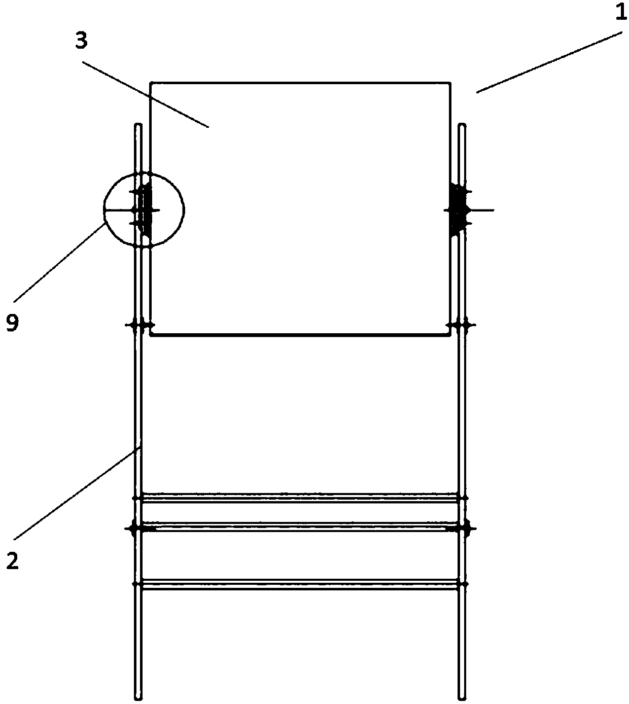
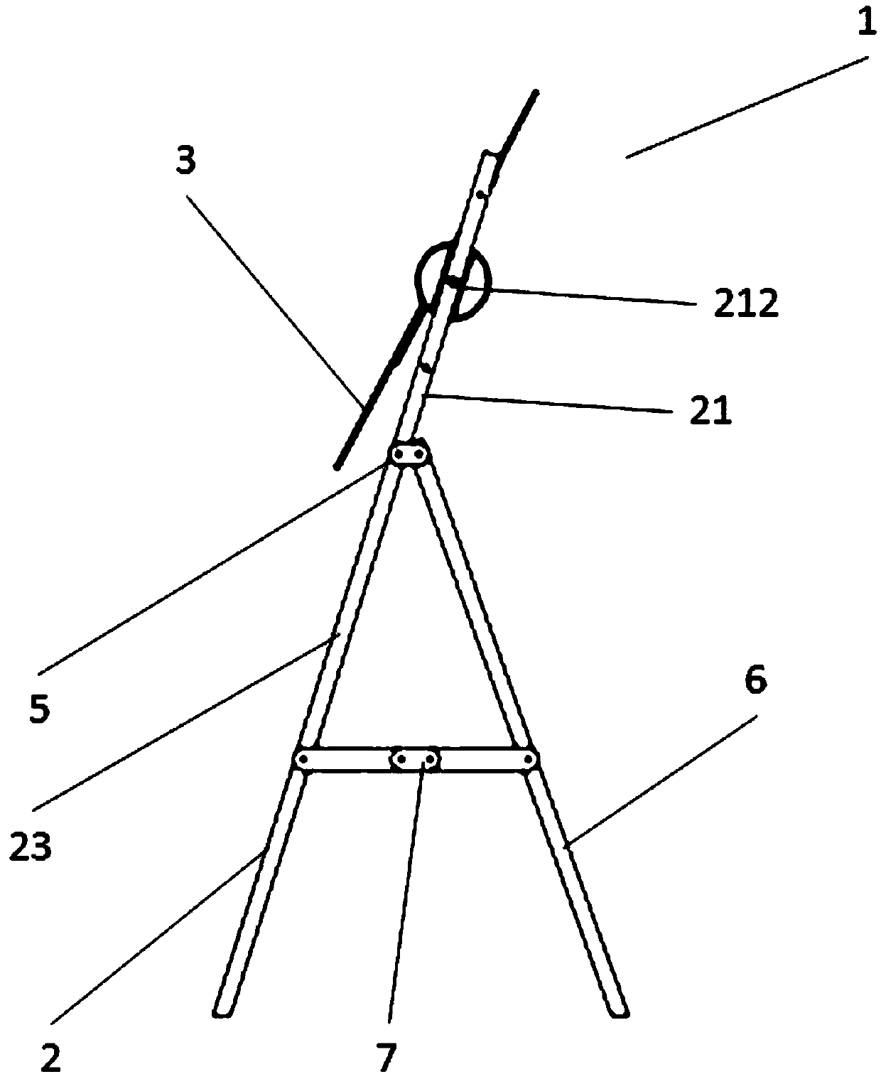
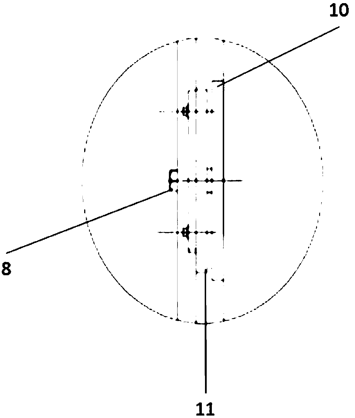
[0020] Please refer to Figure 1 to Figure 4 , are respectively the front schematic diagram and the side schematic diagram of the calibration device of the present ...


PUM


Abstract

The invention discloses a remote laser radar calibration system. The calibration is carried out between a laser radar and a calibration device, and the calibration device is provided with a support, acalibration panel, and an adjustment device. The calibration panel is disposed on the support, and the adjustment device is used for adjusting the height and angle of the calibration panel. The adjustment device comprises a support which is provided with an upper part and a lower part, wherein the upper part is provided with a plurality of adjustment holes at different heights, and the lower partand a folding device are fixed through a connecting device. The adjustment device also comprises an inner rotating control device and an outer rotating control device, wherein the outer rotating control device is disposed between the inner rotating control device and the support, and the inner and outer rotating control devices have the same center. The scale position is read through the mutual rotation of the inner and outer rotating control devices, and the angle is adjusted. In addition, a fixed device can pass through the calibration panel, is disposed on the adjustment holes of the support in a bulged manner, and is fixed on the adjustment holes through a spiral fixing part.

Description

technical field [0001] The invention relates to a device calibration method, in particular to a remote laser radar calibration system and method. Background technique [0002] The LiDAR (light detection and ranging, LiDAR) system can quickly obtain the three-dimensional surface information of the measured object, so as to obtain the high-precision and high-density three-dimensional point cloud data of the measured object. In addition, the full-waveform lidar device can also collect the echo waveform of the measured object through a high-speed analog / digital (A / D) conversion circuit, and form the reflection intensity information of the measured object through waveform analysis. [0003] However, due to the system adjustment and delay interference in the circuit, the system deviation of the laser radar system in the acquisition of scanning angle and distance value is caused. The detector of the radar system has a nonlinear effect during the photoelectric conversion, which cau...

Claims


Application Information

Patent Timeline
Patent Type & Authority Applications(China)
IPC IPC(8): G01S7/497
CPCG01S7/497
Inventor 刘春陈卓周源曾勇
Owner TONGJI UNIV
Learn More