Optimization method for AGC system of steam turbine
An optimization method and steam turbine technology, applied in geometric CAD, computer-aided design, special data processing applications, etc., can solve problems such as difficult to meet the adjustment speed and adjustment accuracy at the same time, achieve improved AGC adjustment speed, wide application range, and improve AGC Adjusting the Effects of Accuracy Issues
- Summary
- Abstract
- Description
- Claims
- Application Information
AI Technical Summary
Problems solved by technology
Method used
Image
Examples
specific Embodiment approach 1
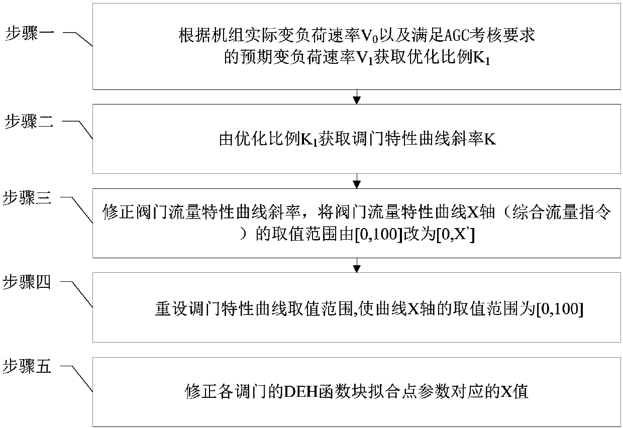
[0032] Specific implementation mode one: as figure 1 Shown, a kind of optimization method of steam turbine AGC system comprises the following steps:
[0033] Step 1: According to the actual variable load rate V of the unit 0 And the expected variable load rate V that meets the requirements of the AGC assessment 1 Get the optimized ratio K 1 ;
[0034] Step 2: According to the optimized ratio K obtained in Step 1 1 Get the slope K of the tuning characteristic curve:
[0035] K=1+K 1
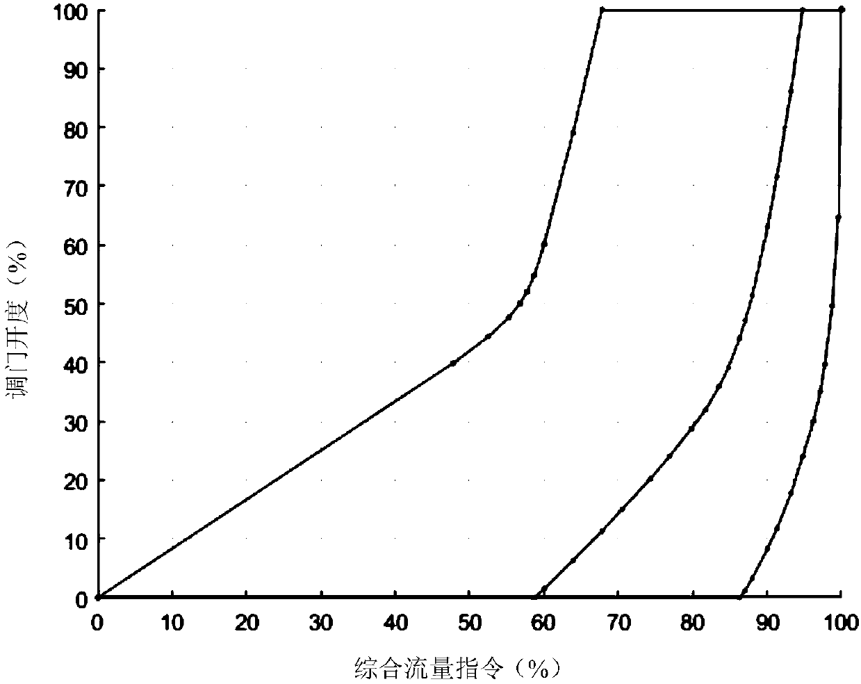
[0036] Step 3: In order to increase the slope of the characteristic curve, change the slope of the valve flow characteristic curve, and change the value range of the valve flow characteristic curve X-axis (comprehensive flow command) from [0,100] to [0,X’], where:
[0037]
[0038] Step 4: Translate the valve flow characteristic curve as a whole, so that the value range of the X-axis of the valve flow characteristic curve is [0,100];
[0039] Step 5: Correct the X value corresponding to...
specific Embodiment approach 2
[0045] Specific embodiment two: the difference between this embodiment and specific embodiment one is that: in the step one, according to the actual variable load rate V of the unit 0 And the expected variable load rate V that meets the requirements of the AGC assessment 1 Get the optimal ratio K 1 Specifically:
[0046]
[0047] Other steps and parameters are the same as those in Embodiment 1.
specific Embodiment approach 3
[0048] Specific embodiment 3: The difference between this embodiment and specific embodiment 1 or 2 is that in the step 4, the overall translation distance X of the valve flow characteristic curve is translated. L for:
[0049] x L = 100-X'.
[0050] Other steps and parameters are the same as those in Embodiment 1 or Embodiment 2.
PUM
 Abstract
Description
Claims
Application Information
 - R&D
- Intellectual Property
- Life Sciences
- Materials
- Tech Scout
- Unparalleled Data Quality
- Higher Quality Content
- 60% Fewer Hallucinations
Browse by: Latest US Patents, China's latest patents, Technical Efficacy Thesaurus, Application Domain, Technology Topic, Popular Technical Reports.
© 2025 PatSnap. All rights reserved.Legal|Privacy policy|Modern Slavery Act Transparency Statement|Sitemap|About US| Contact US: help@patsnap.com


