Computer room equipment over-temperature alarm device

An over-temperature alarm and alarm technology, applied in the direction of electric fire alarm, etc., can solve the problem that the safety and reliability of the equipment cannot be effectively guaranteed, the heating part can only be inspected manually, and the heating point cannot be timely and effective Monitoring and other issues to achieve the effect of easy promotion, safe operation and low cost

Pending Publication Date: 2018-02-09
HBIS COMPANY LIMITED HANDAN BRANCH COMPANY +1
View PDF4 Cites 1 Cited by
  • Summary
  • Abstract
  • Description
  • Claims
  • Application Information

AI Technical Summary

Problems solved by technology

[0002] The high-power equipment in the computer room, such as electrical switchgear, high-voltage cables and connectors, high-current contacts, and large batteries, generally have parts that are prone to heat. Due to the lack of timely and effective tracking and monitoring methods, these heat-generating parts can only be inspected manually at present. check
For closed equipment such as switch cabinets, manual inspections can only measure the temperature of the outside, and cannot directly monitor the heating points inside the equipment in a timely and effective manner. The safety and reliability of the equipment cannot be effectively guaranteed. Therefore, a An online temperature monitoring system suitable for equipment in the computer room is very necessary

Method used


Image

  • Computer room equipment over-temperature alarm device

Examples


Embodiment Construction

[0014] The present invention will be further described below in conjunction with accompanying drawing.

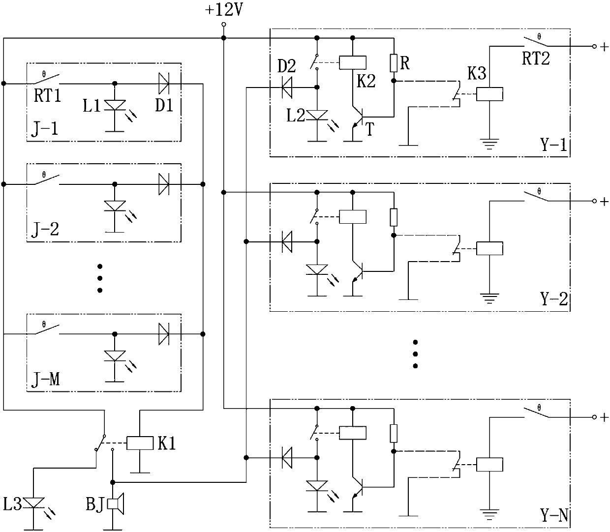
[0015] see figure 1 , the present invention mainly includes 12V switching power supply, sound alarm BJ, alarm relay K1, power indicator light L3, multiple temperature detection units and multiple remote over-temperature monitoring units. The temperature detection unit is used to detect the temperature of the local heating point, and the remote over-temperature monitoring unit is used to monitor the temperature of the remote heating point in the computer room. Under normal circumstances, the control coil of the alarm relay K1 is not energized, the power indicator L3 lights up, and the alarm BJ does not work; when a certain heating point is overheated, the alarm relay K1 operates, the power indicator L3 goes out and the alarm BJ powers on. When connected, an audible alarm signal will be sent to the duty personnel.

[0016] The temperature detection unit includes a thermal s...


PUM


Abstract

The invention relates to a computer room equipment over-temperature alarm device. The computer room equipment over-temperature alarm device is composed of an alarm, an alarm relay and a plurality of temperature detection units; each temperature detection unit comprises a thermal switch, a fault position indication lamp and an isolation diode; the thermal switch is installed on a heat emitting point of computer room equipment; one end of the normally open contact of the thermal switch is connected with the positive pole of a power supply, and the other end of the normally open contact of the thermal switch is connected with the negative pole of the power supply through the isolation diode and the control coil of the alarm relay; one end of the fault position indication lamp is connected with the negative pole of the power supply, and the other end of the fault position indication lamp is connected between the isolation diode and the thermal switch; and the alarm is connected with the power supply through the normally open contact of the alarm relay. According to the computer room equipment over-temperature alarm device of the invention, the thermal switches are adopted to monitor the temperature of each heat emitting point of the computer room equipment in real time; once the temperature of the computer room equipment exceeds a set value, alarm signals are generated to enable on-duty personnel to promptly determine an over-temperature point and eliminate a potential safety hazard, and therefore, accidents such as fires can be effectively avoided, and the safe operation of the high-power equipment of a computer room can be ensured.

Description

technical field [0001] The invention relates to a heating point temperature monitoring and alarm device suitable for high-power equipment in a computer room, and belongs to the technical field of detection. Background technique [0002] The high-power equipment in the computer room, such as electrical switchgear, high-voltage cables and connectors, high-current contacts, and large batteries, generally have parts that are prone to heat. Due to the lack of timely and effective tracking and monitoring methods, these heat-generating parts can only be inspected manually at present. check. For closed equipment such as switch cabinets, manual inspections can only measure the temperature of the outside, and cannot directly monitor the heating points inside the equipment in a timely and effective manner. The safety and reliability of the equipment cannot be effectively guaranteed. Therefore, a An online temperature monitoring system suitable for computer room equipment is very neces...

Claims


Application Information

Patent Timeline
Patent Type & Authority Applications(China)
IPC IPC(8): G08B17/06
CPCG08B17/06
Inventor 陆士冬窦毅
Owner HBIS COMPANY LIMITED HANDAN BRANCH COMPANY
Why Eureka
Try Eureka