Chassis device conveniently separated from seat

A chassis and seat technology, which is used in transportation and packaging, vehicle rescue, patient chairs or special transportation tools, etc., can solve the problems of large assembly workload, increased transportation costs, and complicated connections, and achieves a slot-frame structure. The effect of simplicity, lower production cost and compact box structure

Pending Publication Date: 2018-02-16
NANJING KANGNI MECHANICAL & ELECTRICAL
View PDF2 Cites 2 Cited by
  • Summary
  • Abstract
  • Description
  • Claims
  • Application Information

AI Technical Summary

Problems solved by technology

However, the seat and chassis of most wheelchairs are integrated and inseparable unless mechanically disassembled, which makes it inconvenient to carry. For example, existing wheelchairs (especially electric wheelchairs) cannot be loaded into the trunk of ordinary private cars It is also inconvenient for transportation and maintenance. For example, when transporting electric wheelchairs in batches, each wheelchair will take up a lot of space, which will increase the transportation cost, and it will be difficult to ensure the assembly quality and efficiency if the parts are transported to the bottom and installed; Generally, the seat needs to be disassembled. Due to the complicated connection between the seat and the chassis, the assembly workload after disassembly and repair is large, which makes the maintenance efficiency low.
At the same time, for existing electric wheelchairs, the remote control is located at the upper seat, and it is electrically connected to the lower functional mechanism through an electrical signal line. It is also difficult to separate the electrical connection when the upper seat is separated from the lower chassis.

Method used


Image

  • Chassis device conveniently separated from seat
  • Chassis device conveniently separated from seat
  • Chassis device conveniently separated from seat

Examples


Embodiment 1

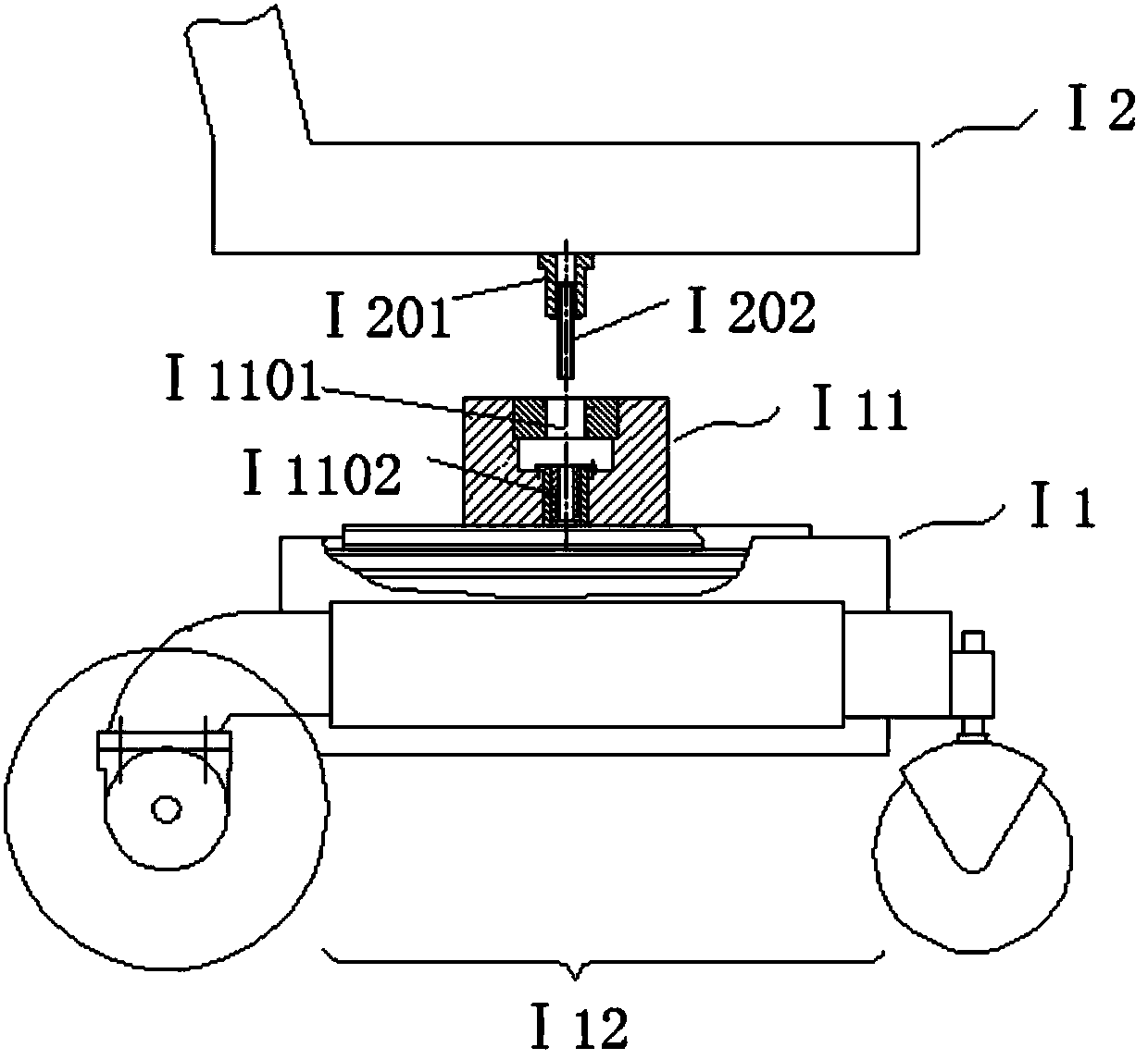
[0064] Such as figure 1 As shown, the chassis device I1 of the present invention includes an electric traveling mechanism I12 and a base I11 arranged above the electric traveling mechanism I12. A support hole I1101 is provided on the upper surface of the base I11, and a multi-core socket I1102 is provided below the support hole I1101. The upper seat device I2 is inserted into or pulled out of the support hole I1101 through the insertion shaft I201 provided below, and at the same time, the multi-core plug I202 provided at the lower end of the insertion shaft I201 is inserted into or pulled out of the multi-core socket I1102 on the base to connect with the chassis device Ⅰ1 connection or separation.

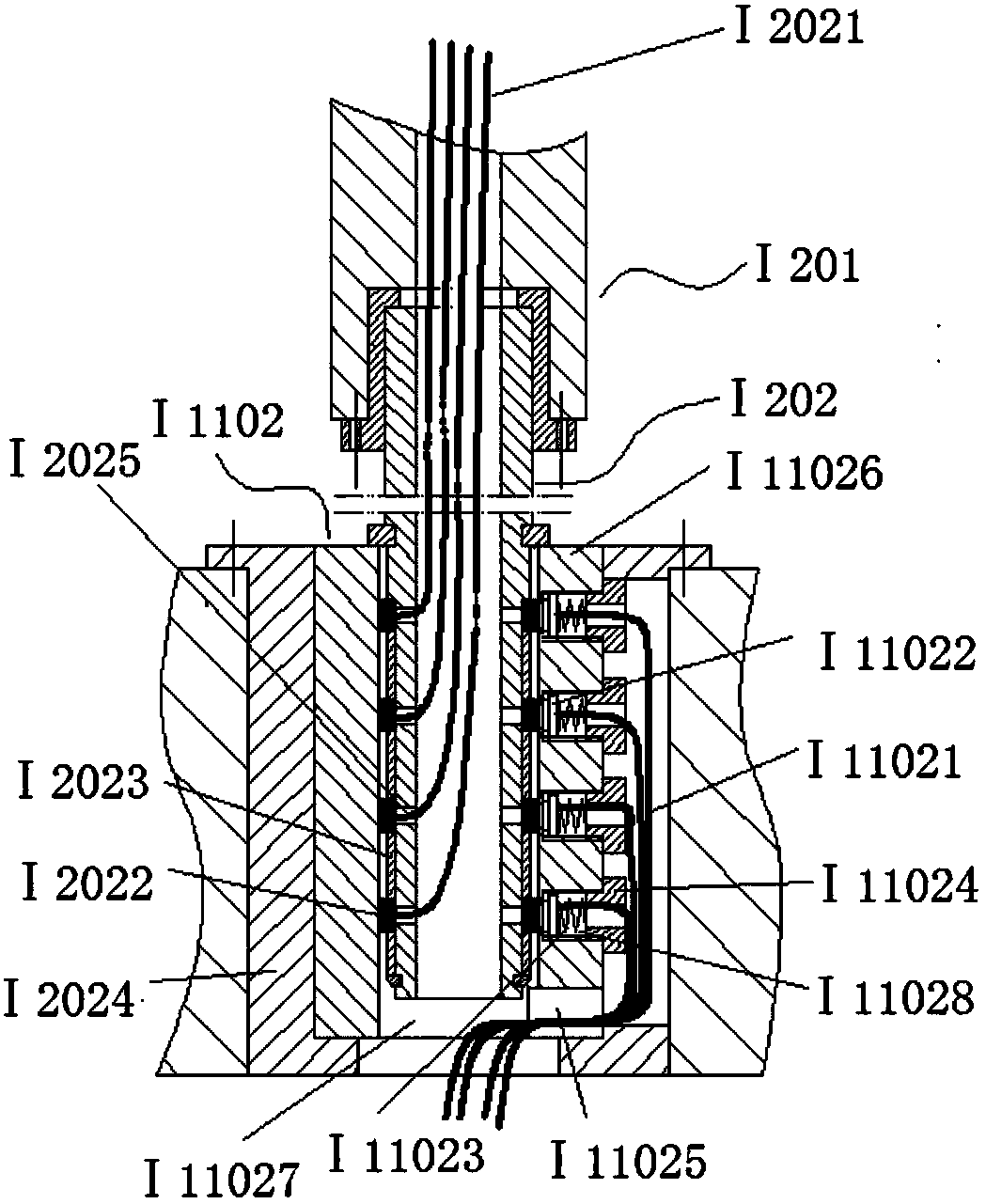
[0065] Such as figure 2As shown, the multi-core plug I202 includes a plug body I2024, a first electrical connection terminal I2022, an insulating ring I2023 and a first electrical connection wire I2021. The plug body I2024 is a hollow tube made of insulating material, and the ci...

Embodiment 2

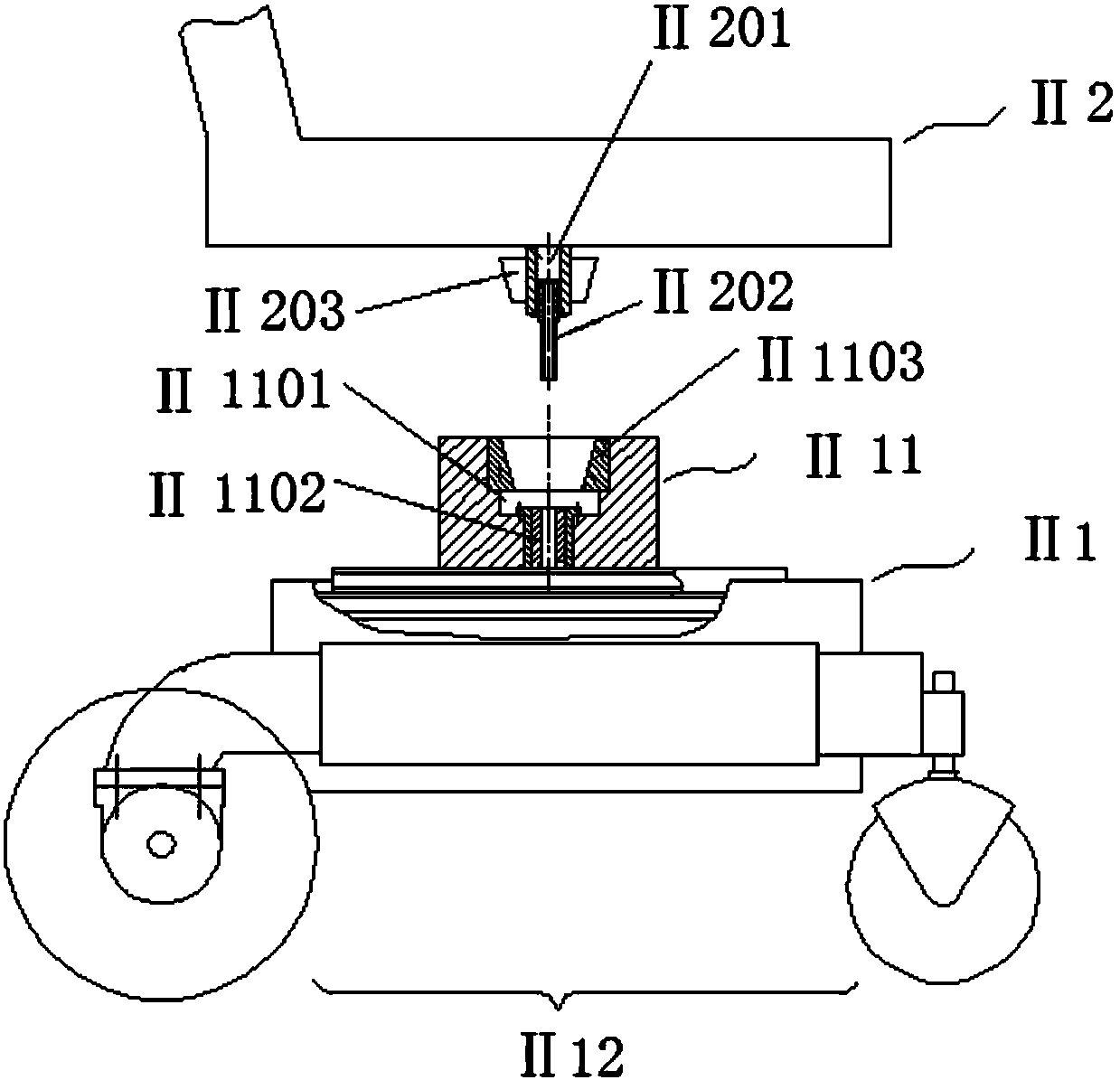
[0069] Such as image 3 As shown, the chassis device II1 of the present invention includes an electric traveling mechanism II12 and a base II11 arranged above the electric traveling mechanism II12. A support hole II1101 is provided on the upper surface of the base II11, a support sleeve II1103 is provided in the support hole II1101, and a multi-core socket II1102 is provided below the support hole II1101. Below the seat device II2 connected to the chassis device II1 in this embodiment, there is a rotating shaft II201, and a rotating body II203 is arranged on the rotating shaft II201. The rotating body II203 adopts a rotating body in a tapered roller bearing. The inner ring, the cage connected to the inner ring of the bearing and the tapered rollers supported on the cage are composed. The rotating body II203 is connected to the rotating shaft II201 through the inner ring of the bearing, and the supporting sleeve II1103 is the bearing outer ring of the rotating body, so that Th...

Embodiment 3

[0071] In order to better realize the rotation function of the upper seat device, the structure of the base II11 in Embodiment 2 is as follows: Figure 4 shown. The base II11 adopts the profile design, including the upper end plate II111 arranged along the length direction of the profile, the accommodation cavity arranged under the upper end plate II111, the positioning rib plate II117, the guide rib, the connecting shaft hole II115, the forming hole II1122 and the swing shaft hole II116 . The positioning rib plate II117 has at least a positioning plane parallel to the upper end plate II111, and divides the accommodation cavity into an upper accommodation cavity II112 and a lower accommodation cavity II113 distributed up and down, and two sets of guide ribs II114 are arranged on both sides of the lower accommodation cavity II113, separating There are two side accommodation chambers II 1131 and the middle chamber, and one of the side accommodation chambers II 1131 is used to p...


PUM


Abstract

The invention discloses a chassis device conveniently separated from a seat. The chassis device is connected with an upper seat device to form an electric wheelchair; the chassis device comprises an electric walking mechanism arranged at the lower end; the chassis device further comprises a base; the base is arranged at the upper end of the electric walking mechanism; a bearing hole is formed in the upper end face of the base; a multi-core socket or a multi-core plug is arranged on the base below the bearing hole coaxial with the bearing hole, and the base is electrically connected with a multipath signal line through the multi-core plug or the multi-core socket. Through the formation of the bearing hole, the chassis device is conveniently in butt joint with an inserting shaft of the upperseat device, quick mechanical disassembly and assembly are achieved, the convenience of the wheelchair is improved, and aiming at the electric wheelchair, through a multi-core plugging unit arrangedon the base, a function mechanism on the lower chassis is conveniently and electrically connected with and quickly and electrically split with a remote control unit arranged on the upper portion.

Description

technical field [0001] The invention relates to a wheelchair, in particular to a chassis device which is convenient to be separated from a seat. Background technique [0002] As a means of transportation for the physically disabled and the elderly, wheelchairs bring certain convenience. Ordinary wheelchairs generally consist of two parts, the upper seat and the lower chassis. The electric wheelchair improves the traveling mechanism provided on the lower chassis into an electric traveling mechanism, which is convenient for control. However, the seat and chassis of most wheelchairs are integrated and inseparable unless mechanically disassembled, which makes it inconvenient to carry. For example, existing wheelchairs (especially electric wheelchairs) cannot be loaded into the trunk of ordinary private cars It is also inconvenient for transportation and maintenance. For example, when transporting electric wheelchairs in batches, each wheelchair will take up a lot of space, whi...

Claims


Application Information

Patent Timeline
IPC IPC(8): A61G5/04A61G5/10
CPCA61G5/04A61G5/10A61G2220/14
Inventor 金元贵柯旭叶华雷郑海李鹏尹琨
Owner NANJING KANGNI MECHANICAL & ELECTRICAL
Why Eureka
Try Eureka