

Unmanned aerial vehicle control plane drive mechanism
A technology of driving mechanism and rudder surface, which is applied in the field of unmanned aerial vehicles, can solve the problems of unsophisticated and beautiful appearance of unmanned aerial vehicles, complicated disassembly and replacement of rudder surfaces, leakage of drive transmission mechanism, etc., so as to achieve simple and direct driving mode, The appearance is simple and the effect of increasing the reliability of the mechanism
- Summary
- Abstract
- Description
- Claims
- Application Information
AI Technical Summary
Problems solved by technology
Method used
Image

Examples
Embodiment 1
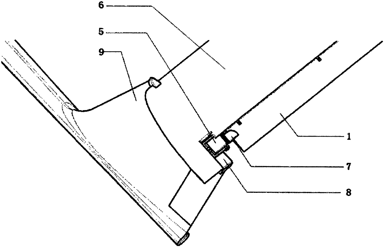
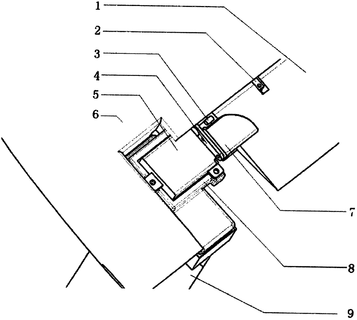
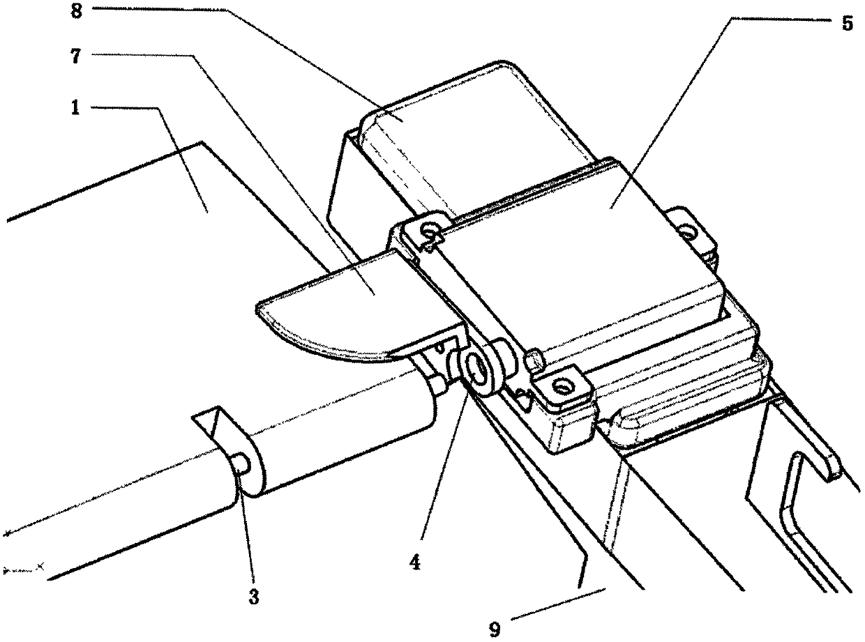
[0022] Such as Figure 1-4 As shown, the present invention provides a UAV rudder surface driving mechanism, including elevator 1, Y-shaped chuck 2, elevator shaft 3, rocker arm 4, elevator steering gear 5, horizontal stabilizer 6, rudder surface clip 7, flat tail rudder Machine base 8 and vertical tail part 9, one side of elevator 1 is provided with Y-shaped chuck 2, and Y-shaped chuck 2 clamps elevator shaft 3, and elevator steering gear 5 is provided with rocker arm 4, and rocker arm 4 is provided with The rudder surface clip 7, the elevating steering gear 5 are fixed on the flat tail steering gear base 8, and the flat tail steering gear base 8 is installed on the vertical tail part 9.
[0023] The elevating steering gear 5 directly drives the rudder surface to rotate through the rocker arm 4 and the rudder surface clamp 7 fixedly connected with the driving teeth, the flat tail steering frame 8 is fixedly connected with the vertical tail part 9, and the lifting steering gear...
PUM
 Abstract
Description
Claims
Application Information