
Rail fastening system and insulation method thereof

A technology for steel rails and fasteners, which is applied in the field of railway track component manufacturing, can solve the problems of the under-rail backing plate not contributing to the insulation of the fastener, the under-plate backing plate failing to insulate, and the insulating paint failing to insulate. , to achieve the effect of improving reliability and safety, reducing stray current, high safety and reliability

Inactive Publication Date: 2018-02-16
ZHUZHOU TIMES NEW MATERIALS TECH
View PDF9 Cites 4 Cited by
  • Summary
  • Abstract
  • Description
  • Claims
  • Application Information

AI Technical Summary

Problems solved by technology

[0009] 1. The spike is the main fastening part of the entire fastener system. Since the spike is exposed and has no protective parts, it is easily polluted by the environment, which leads to the conduction between the spike and the sleeper, and the backing plate under the board cannot achieve good insulation effect;
[0010] 2. The iron backing plate is directly connected to the spring bar. When there is dust and water on the surface, the insulating paint cannot insulate and form a conduction. The backing plate under the rail does not contribute to the insulation of the fastener;
[0011] 3. Although the gauge block plays an insulating role, the improvement of the insulation performance of the entire fastener system is not obvious

Method used


Image

  • Rail fastening system and insulation method thereof
  • Rail fastening system and insulation method thereof

Examples


Embodiment Construction

[0031] Combine below Figure 1 to Figure 2 The embodiments of the present invention will be described in detail.

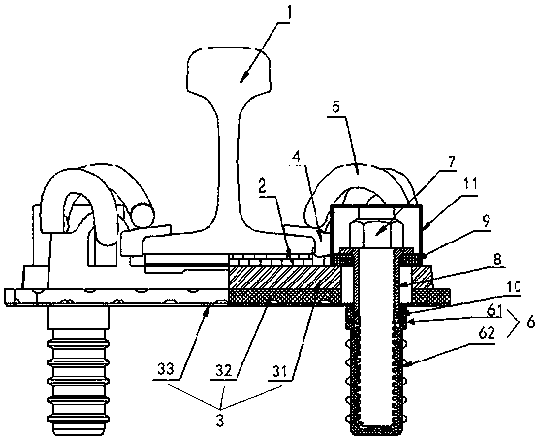
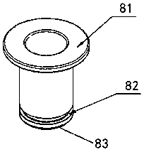
[0032] The rail fastener system includes an under-rail pad 2 under the rail 1, an insulating elastic pad 3 under the under-rail pad 2, and an insulating gauge block 4 pressed on the rail 1, for pressing and insulating The elastic strip 5 of the gauge block 4, the sleeve 6 embedded in the sleeper and the spike 7 fastened in the sleeve 6 through the insulating elastic backing plate 3 are characterized in that the screw of the spike 7 is An insulating sleeve 8 is sheathed in the half section. The lower end of the insulating sleeve 8 extends into the sleeve 6 and is in a sealing fit with the sleeve 6, and the upper end is clamped between the spike 7 and the insulating elastic backing plate 3.

[0033] Such as figure 1 As shown, the upper end of the insulating sleeve 8 separates the spike 7 from the insulating elastic backing plate 3 to prevent the spikes 7 from being conn...


PUM


Abstract

The invention provides a rail fastening system. The rail fastening system comprises an under-rail backing plate padded under a rail, an insulated elastic backing plate padded under the under-rail backing plate, an insulated gauge block pressed on the rail, an elastic strip for tightly pressing the insulated gauge block, a sleeve pipe pre-buried in a sleeper, and a rail spike which passes through the insulated elastic backing plate and is fastened in the sleeve pipe. The rail fastening system is characterized in that the upper section of a screw rod of the rail spike is sleeved with an insulated sleeve, the lower end of the insulated sleeve extends into the sleeve pipe and is hermetically matched with the sleeve pipe, and the upper end of the insulated sleeve is clamped between the rail spike and the insulated elastic backing plate. The rail fastening system provided by the invention has the advantages that an existing rail fastening is structurally improved according to the reduction reason of the insulation property of the fastening system, the insulation property of the rail fastening system in a severe environment is enhanced, formation of stray current is reduced, corrosion tomunicipal pipelines is reduced, and the rail fastening system has higher use safety and reliability. The invention also provides an insulation method of the rail fastening system.

Description

Technical field [0001] The invention relates to a rail fastener system and an insulation method thereof, which are used to improve the insulation performance of the rail fastener system and belong to the field of railway track assembly manufacturing. Background technique [0002] Today's rail transit is developing rapidly. In this series of construction, the fastener system is indispensable. It fixes the rails and provides elasticity and insulation in the track structure. At present, the commonly used spike-type spring bar fastener system is mainly composed of a base part, a spring bar part compressed by a spike, a gauge stop part that adjusts the gauge and acts as insulation, and a backing plate part that provides track elasticity . [0003] In DC electrical transportation systems such as urban subways and light rails, this fastener system uses steel rails as return lines. Because the existing rail installation technology cannot achieve complete ground insulation, some current wi...

Claims


Application Information

Patent Timeline
IPC IPC(8): E01B9/30
CPCE01B9/303E01B2201/04E01B2201/08E01B2205/00
Inventor 楚纯朋颜湘龚颖强邓娇胡启科李金卫齐西雷
Owner ZHUZHOU TIMES NEW MATERIALS TECH
Learn More