Z-shaped steel plate combined shear wall with stiffening ribs arranged in staggered mode

A combined shear wall, staggered arrangement technology, applied in the direction of walls, building components, buildings, etc., can solve the problems of small mechanical bite force, high construction cost, low out-of-plane stiffness, etc., to increase the mechanical bite force and improve the overall performance. , to ensure the effect of compactness

Inactive Publication Date: 2018-02-16
QINGDAO TENGYUAN DESIGN ACCOUNTANTS CO LTD
View PDF2 Cites 2 Cited by
  • Summary
  • Abstract
  • Description
  • Claims
  • Application Information

AI Technical Summary

Problems solved by technology

Traditional reinforced concrete shear walls require multiple construction procedures on the construction site, such as setting up formwork, binding steel bars, pouring concrete, curing, and removing formwork. The construction period is long and the construction cost is high.
The steel plate shear wall is a lateral force-resisting component developed in the 1970s. It is small in size and light in weight, which can increase the usable area of ​​the house and reduce the cost of the foundation. Under the action of a small horizontal load, there will be out-of-plane drumming, which will affect the appearance of the building. In addition, the "squeak" noise accompanied by the drumming will affect the comfort of the building.
Patent CN105821989A proposes a prefabricated steel tube beam concrete shear wall structure system. Its basic unit, the prefabricated inline steel tube beam concrete shear wall, is formed by connecting several U-shaped steel tube units and rectangular steel tube units. Concrete is poured inside the steel tubes. , the components of this structure can be standardized design, industrial production, and assembly construction, and the production efficiency is high, but the surface of the steel plate is smooth, the mechanical bite force between the concrete and the steel pipe is small, and the independent steel pipe units are easy to cause the concrete to be poured. These reasons Both will cause adverse effects on structural performance; patent CN205206087U proposes a web opening type composite structure shear wall, and concrete is poured in the steel beam to form the shear wall, wherein the steel beam is provided with through holes on multiple webs It is composed of side-by-side tailor-welded H-beams, but due to the small size of the through-holes on the web and the size of the beams, the concrete is not easy to be poured densely.

Method used


Image

  • Z-shaped steel plate combined shear wall with stiffening ribs arranged in staggered mode
  • Z-shaped steel plate combined shear wall with stiffening ribs arranged in staggered mode

Examples


Embodiment 1

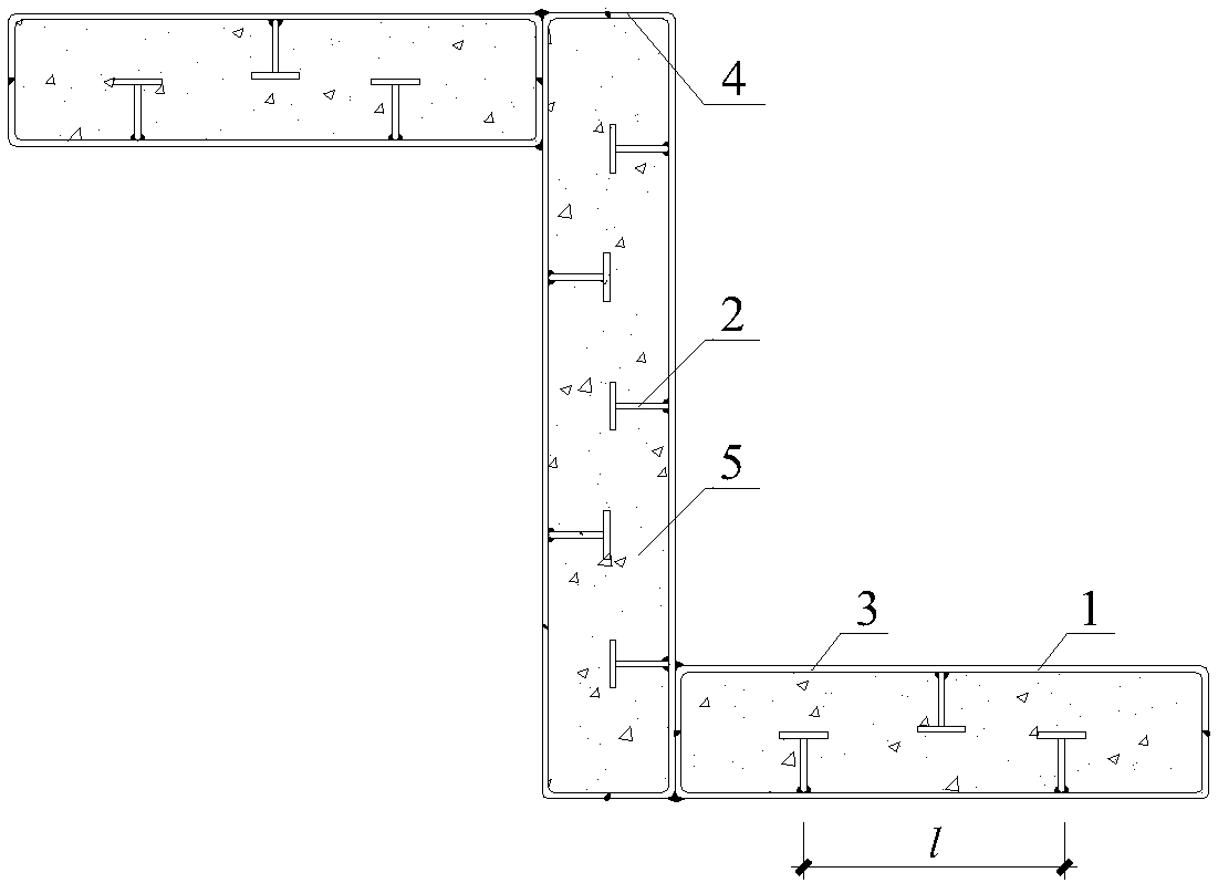
[0012] A Z-shaped steel plate composite shear wall with staggered stiffeners, including a channel member 1, a stiffener 2, and concrete 5, and T-shaped stiffeners 2 are arranged on the web 3 of the channel member according to the design requirements to form a ribbed channel The distance between adjacent stiffeners 2 is l, and the value of l is 2 to 4 times the height of the flange 4 of the channel-shaped steel plate; design another channel-shaped member 1, T-shaped stiffener 2 and the first channel-shaped The members 1 are arranged in a staggered manner, and the flanges 4 of the two grooved members are welded to form a rectangular cavity; the short sides of the two rectangular cavities are respectively welded to the two ends of the long side of the other rectangular cavity to form a Z-shaped cavity; Pour concrete 5 in the cavity.

Embodiment 2

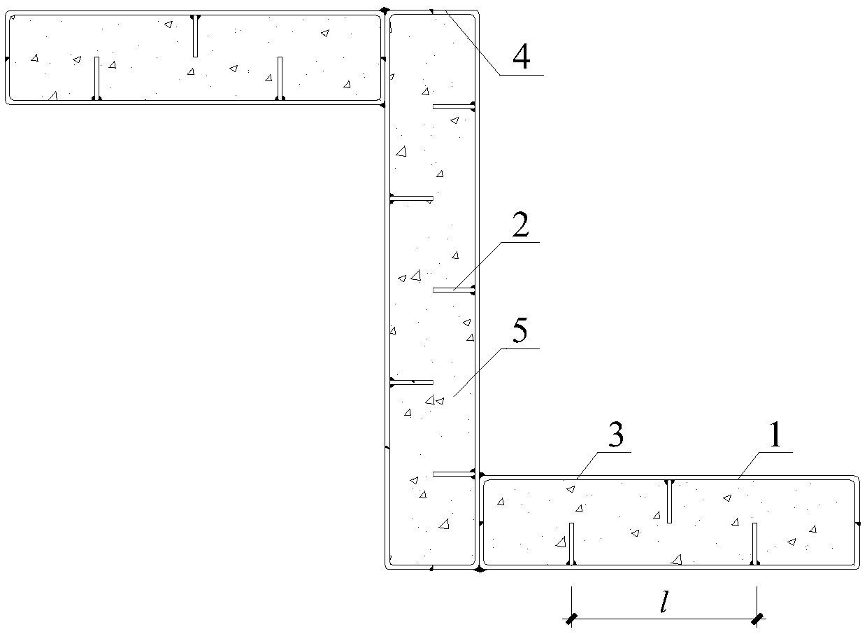
[0014] The difference from Example 1 is that the form of the stiffener is Type I.


PUM


Abstract

The invention belongs to the field of shear wall structure design, and relates to a Z-shaped steel plate composite shear wall with staggered arrangement of stiffeners. According to the design requirements, stiffeners are arranged on the web of the channel member to form a ribbed channel member; another channel member is designed, the stiffeners are arranged alternately with the first one, and the flanges of the two channel members are welded to form a rectangle Cavity; welding the short sides of two rectangular cavities to the two ends of the long side of another rectangular cavity respectively to form a Z-shaped cavity; pouring concrete in the cavity. Stiffeners are arranged on the web of the trough-shaped member, which is conducive to increasing the mechanical bite force between the concrete and the steel plate, ensuring that the two work together and improving the overall performance of the structure; in the rectangular cavity formed by the two trough-shaped members, the stiffener The ribs are arranged in a staggered manner, which makes the interior of the rectangular cavity run through, and when the cavity is poured with concrete, it is easy to vibrate and ensure the compactness of the concrete.

Description

technical field [0001] The invention belongs to the field of shear wall structure design, and relates to a Z-shaped steel plate composite shear wall with staggered stiffening ribs. Background technique [0002] With the development of the economy, the urban population is becoming more and more dense, but land resources are becoming more and more scarce. In order to solve the problem of more people and less land, high-rise buildings have been erected one after another. For multi-story buildings, horizontal loads have little effect on their mechanical properties, and vertical loads play a controlling role; while for high-rise and super high-rise buildings, horizontal loads play a major role in controlling them, so the building structure must have sufficient lateral stiffness to resist horizontal loads. [0003] In high-rise building structures, shear walls are the most commonly used lateral force-resisting members. Traditional reinforced concrete shear walls require multiple...

Claims


Application Information

Patent Timeline
IPC IPC(8): E04B2/58
CPCE04B2/58
Inventor 郁有升胡海涛李建峰井彦青王磊高履伟
Owner QINGDAO TENGYUAN DESIGN ACCOUNTANTS CO LTD
Why Eureka
Try Eureka