Liquid cooling method and device

A cooling device and fluid technology, applied in water shower coolers, lighting and heating equipment, heat exchanger types, etc., can solve problems such as insufficient cooling capacity

Active Publication Date: 2019-12-03
TIANJIN UNIV
View PDF8 Cites 0 Cited by
  • Summary
  • Abstract
  • Description
  • Claims
  • Application Information

AI Technical Summary

Problems solved by technology

In addition, the method of spraying water at the air inlet to reduce the humid air to close to the wet bulb temperature and exchange heat with the fins can also enhance the heat exchange capacity of the fins, but in fact it is only the cooled air that exchanges heat with the fins. Although the cooling capacity has been improved, the heat exchange between the humid air and the fins after water vaporization and cooling still belongs to the method of only heat conduction cooling, and the cooling capacity of water vaporization has not been fully utilized

Method used


Image

  • Liquid cooling method and device
  • Liquid cooling method and device
  • Liquid cooling method and device

Examples


Embodiment 1

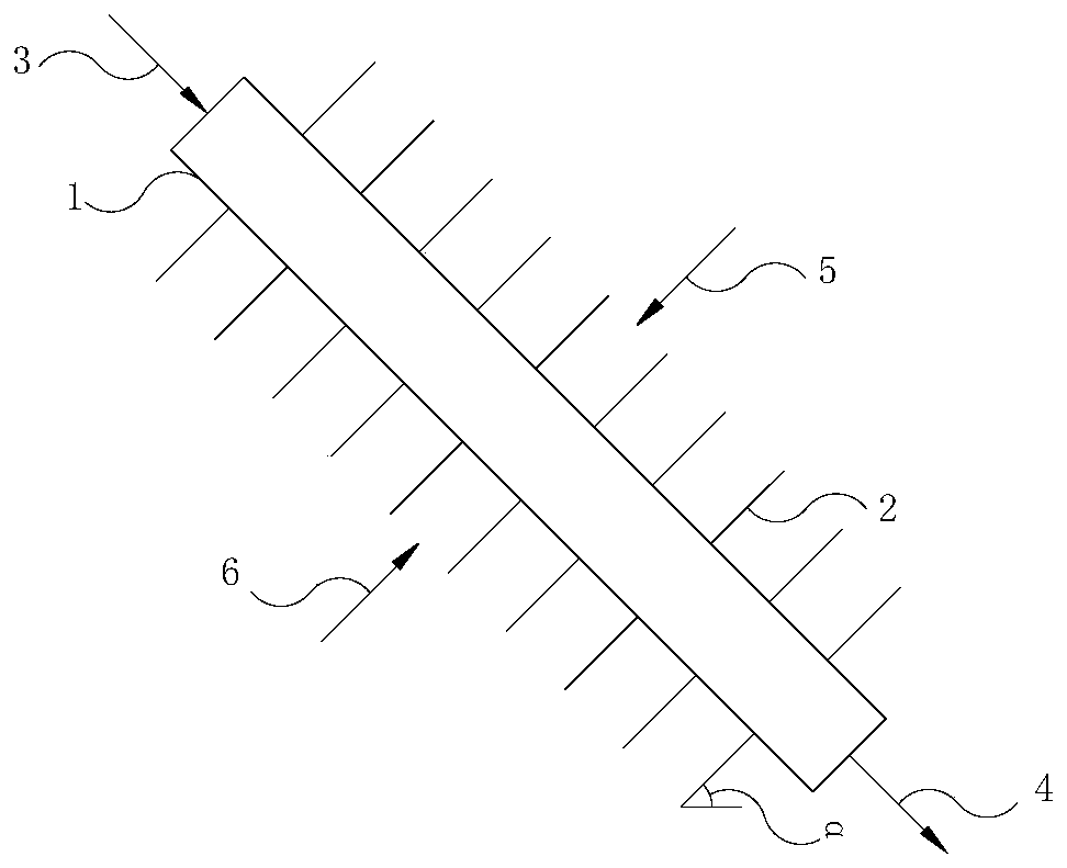
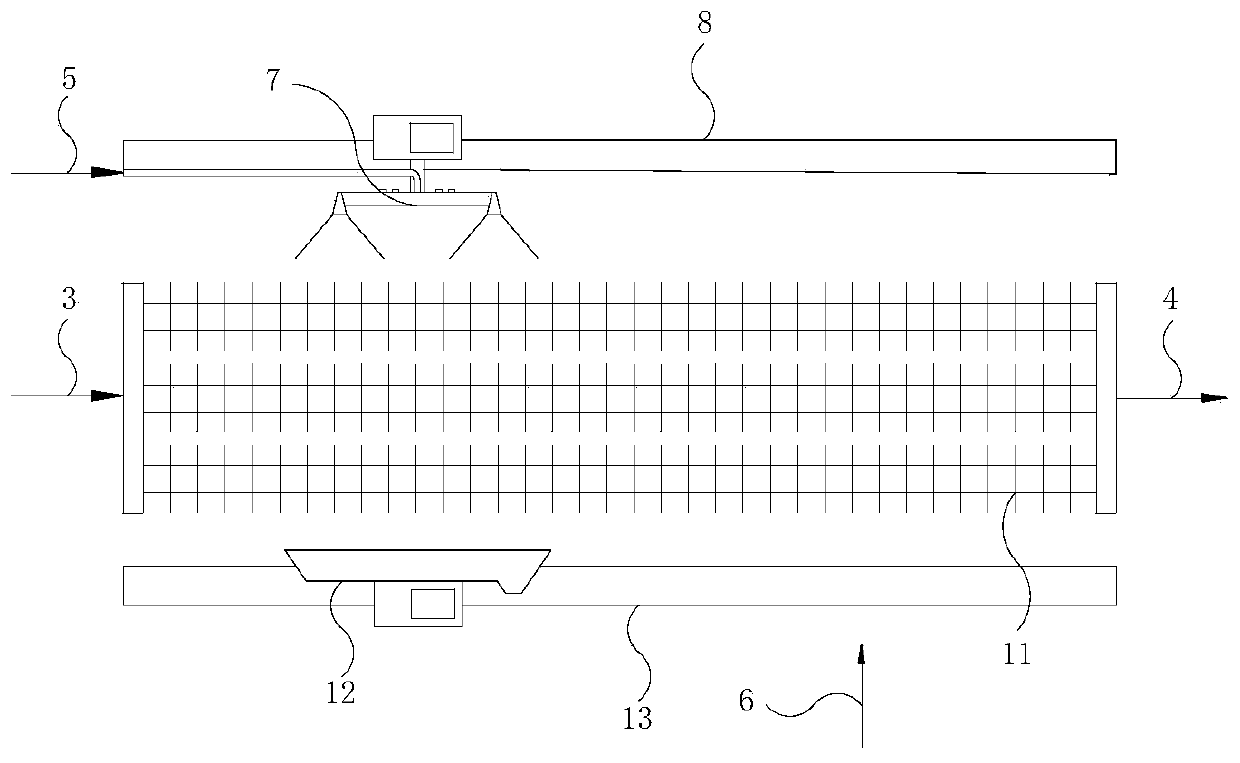
[0038] This embodiment is a cooling scheme for circulating cooling water in the metallurgical industry, such as Figure 4 shown. The cooling system is composed of finned tubes 16 at the upstream section of the fluid tube and finned tubes 17 at the downstream section of the fluid tube connected in series. The hot fluid 3 of the circulating cooling water enters the finned tube 16 in the upstream section of the fluid tube, is cooled by the circulating air 6, and then passes through the upstream and downstream fluid pipeline connection tube 15 and enters the finned tube 17 in the downstream section of the fluid tube, and is further absorbed by the air and water film water. After evaporative cooling and cooling, the finned tubes flow out, and the cold fluid 24 that does not pass through the cold water storage tank is sent to the user as the cold fluid 24 of circulating cooling water. The angle between the fins and the horizontal plane is 45°. The upper surface of the fins is coate...

Embodiment 2

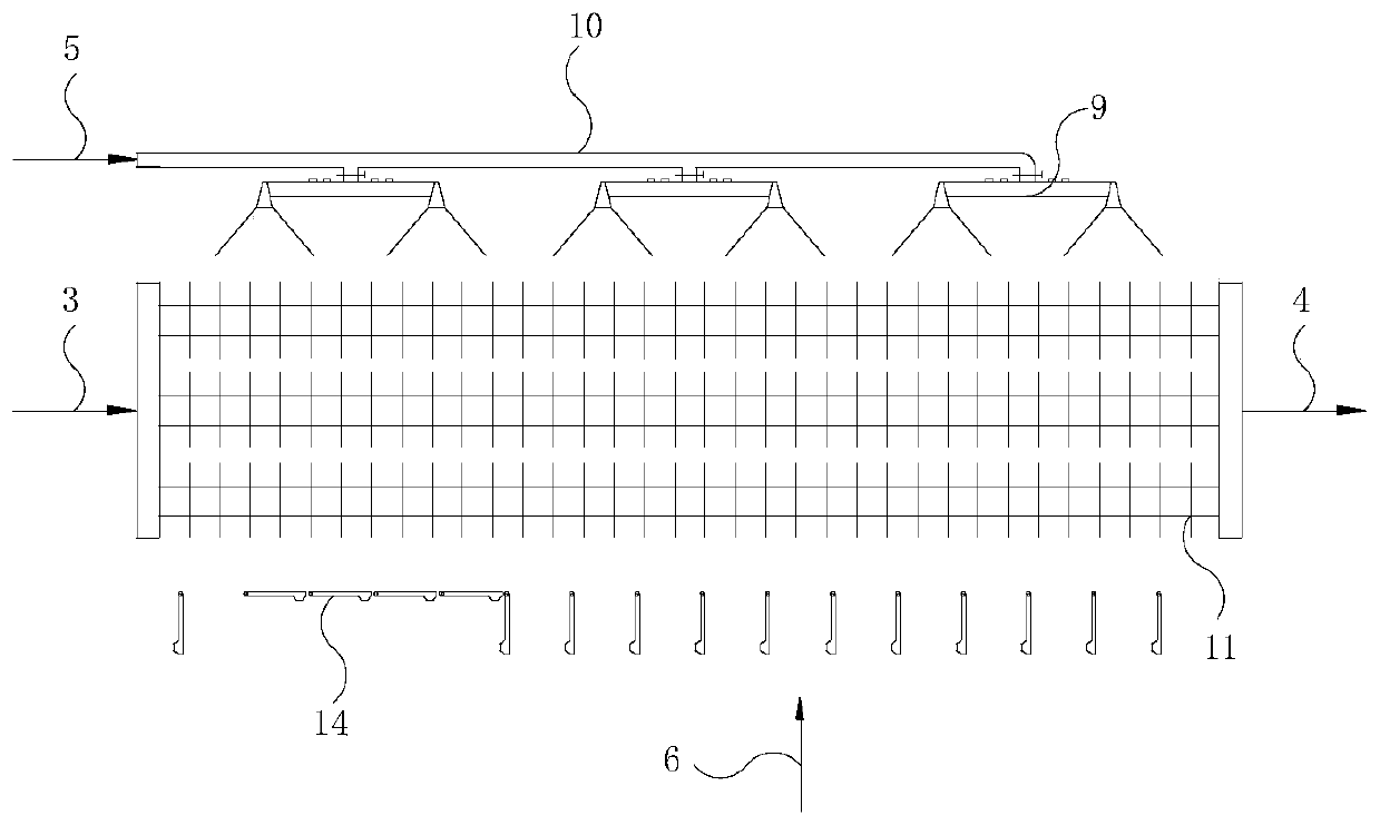
[0042] This embodiment is a cooling scheme for circulating cooling water in the metallurgical industry, such as Figure 5 shown. The cooling system is composed of a finned tube 16 at the upstream section of the fluid tube and a heat exchange metal tube 25 at the downstream section of the fluid tube connected in series. Circulating cooling water enters the finned tube 16 in the upstream section of the fluid tube, is cooled by the circulating air 6, and then enters the heat exchange metal tube 25 in the downstream section of the fluid tube, and is further cooled by the air and water film water, and then flows out of the heat exchange metal tube to the user . The angle between the fins in the upstream section of the fluid tube and the horizontal plane is 75°, the upper and lower surfaces of the fins on the finned tubes are coated with a hydrophilic paint layer, the outer surface of the heat exchange metal tube is coated with a hydrophilic paint layer, and the fins in the upstrea...

Embodiment 3

[0046] This embodiment is basically the same as Embodiment 1, the difference is that in the high temperature season, the strengthening of the cooling capacity uses water evaporation heat exchange, instead of installing a water distribution device on the upper part of the finned tube to distribute water to the fins, but at the air inlet The side is equipped with a water spray mechanism that sprays water into the air, such as Figure 6 shown. Using atomized water to evaporate in the air, the air inlet temperature can be lowered from the dry bulb to close to the wet bulb temperature. At the same time, the air entrains the sprayed water into the fin space, and the water droplets form a water film on the hydrophilic fin, which can also be realized The latent heat of water vaporization of the water film absorbs the heat and forces the evaporation heat exchange function, which obtains a higher heat extraction capacity than ordinary air cooling. Although the cooling effect of this me...


PUM


Abstract

The invention relates to a fluid cooling method and device. The device comprises an air cooler. The air cooler at least comprises finned tubes composed of fluid pipes and fins, wherein cooled fluid circulates in the fluid pipes, and the fins are connected with the outer sides of the fluid pipes, arranged at intervals and composed of flaky thin plates. The single side or two sides of the surface ofeach flaky thin plate are coated with a hydrophilic coating layer or hydrophilic coating layers. The flaky thin plates are in contact with circulating air. During cooling of the air cooler to the fluid, water is distributed to the finned tubes in the time frame of high atmospheric temperature, and in the time frame of low atmospheric temperature, no water is distributed to the finned tubes, or water is distributed to the finned tubes in a segmentation manner. According to the fluid cooling method and device, the surfaces of the fins are coated with hydrophilic coating, uniform and stable water films are formed on the surfaces of the fins in a wind blocking and water distribution manner, in the atmosphere high temperature time frame, water film water vaporization latent heat absorption, forced evaporation and heat exchange are directly carried out on the fins, and the cooling capacity of equipment is greatly improved. The fluid cooling method and device have the beneficial effects of being remarkable in water saving effect, low in investment cost and low in operating cost.

Description

technical field [0001] The invention relates to a fluid cooling method and device, especially for the cooling of circulating cooling water and the condensation of steam in industrial processes, using water evaporation and heat exchange to make up for the lack of cooling capacity of air in high temperature periods, ensuring the cooling cycle of circulating cooling water Utilizing the effect of condensation of steam and achieving the purpose of reducing the scale of the device, saving equipment investment and operating costs, it belongs to the field of industrial water circulation, industrial cooling and air cooling water saving. Background technique [0002] In order to ensure the normal operation of industrial production processes, many processes need to be cooled. Due to its low price, abundant resources, and excellent heat transfer performance, natural water is often used as a heat transfer medium for industrial cooling, called cooling water. Cooling water is the largest ...

Claims


Application Information

Patent Timeline
Patent Type & Authority Patents(China)
IPC IPC(8): F28C1/00F28F25/02
CPCF28C1/00F28F25/02
Inventor 张书廷刘栩雯田津
Owner TIANJIN UNIV
Why Eureka
Try Eureka