Smart home testing system and method thereof

A smart home and detection system technology, applied in general control systems, control/adjustment systems, instruments, etc., can solve problems such as inability to send, inability to know the action of home appliances, and inability to determine home appliances, so as to improve user experience

Inactive Publication Date: 2018-02-16
XIAMEN INTRETECH
View PDF6 Cites 1 Cited by
  • Summary
  • Abstract
  • Description
  • Claims
  • Application Information

AI Technical Summary

Problems solved by technology

Since infrared transmission is a one-way communication, the intelligent controller or smart home gateway with infrared transmission or learning can intelligently confirm whether an infrared signal has been transmitted to the home appliance, but it cannot be sure whether the home appliance has received the infrared signal or received the infrared signal. Whether the relevant operation was actually performed when the signal was issued
Moreover, when using infrared signals to control home appliances, since the signals are transmitted through light, if there is an object between the infrared transmitter and the infrared receiver of the controlled home appliance, the infrared signal will be blocked and cannot be sent to the corresponding home appliance. equipment
Therefore, in practical applications, after the user sends a control signal through the terminal device, he cannot know whether the home appliance has executed the corresponding action, which makes the user experience poor.

Method used


Image

  • Smart home testing system and method thereof
  • Smart home testing system and method thereof
  • Smart home testing system and method thereof

Examples


no. 1 example

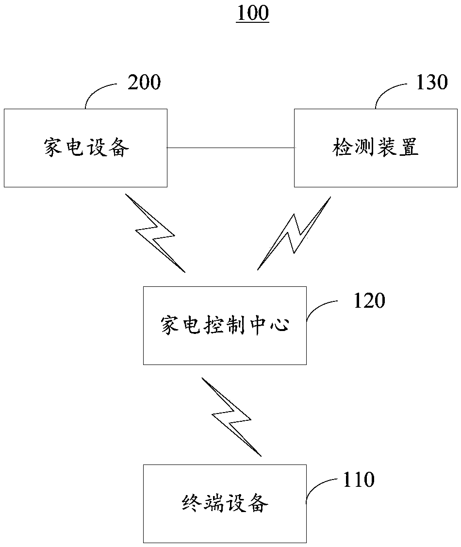
[0030] Please refer to figure 1 , Is a schematic diagram of the composition of the smart home detection system 100 provided by the first embodiment of the present invention. The smart home detection system 100 can be used to control the operation of the home appliance 200, which includes a terminal device 110, a home appliance control center 120, and a detection device 130. The home appliance control center 120 and the terminal device 110, the detection device 130, and the home appliance Both 200 are in communication connection, and the detection device 130 is electrically connected with the household appliance 200.

[0031] The home appliance control center 120 is used to receive the control signal sent by the terminal device 110, and control the home appliance 200 to perform corresponding actions according to the control signal.

[0032] Specifically, the user can send a control signal (for example, turn on or turn off the air conditioner) to the home appliance control center 120...

no. 2 example

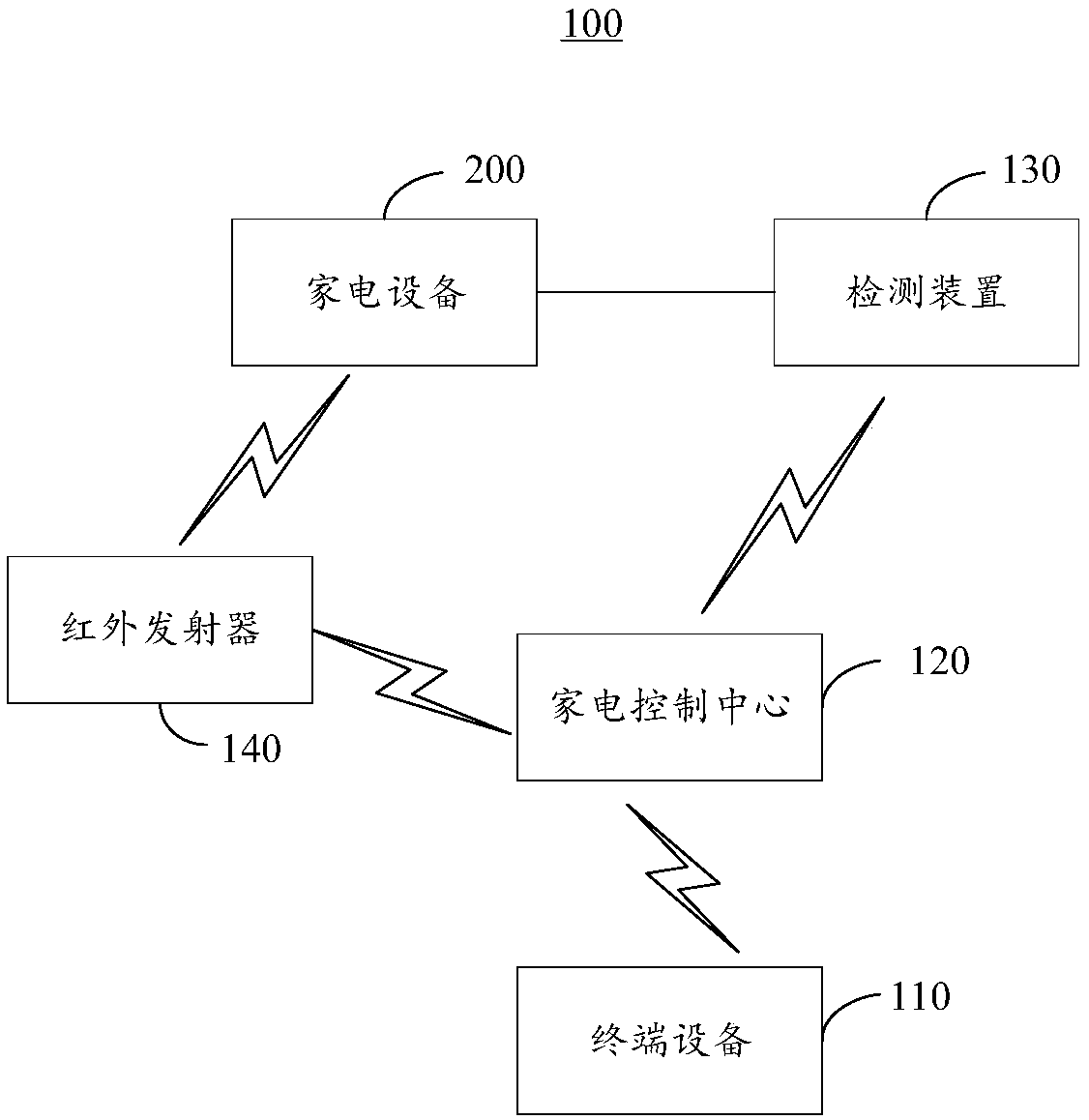
[0041] Please refer to figure 2 , Is a schematic diagram of the composition of the smart home detection system 100 provided by the second embodiment of the present invention. Compared with the smart home detection system 100 provided in the first embodiment, the smart home detection system 100 provided in the second embodiment of the present invention further includes an infrared transmitter 140, which is connected to the home appliance 200 and The home appliance control centers 120 are all connected in communication.

[0042] In this embodiment, the home appliance control center 120 is used to control the infrared transmitter 140 to send infrared instructions to the home appliance 200 according to the control signal, so that the home appliance 200 executes the corresponding infrared command according to the infrared instruction. Actions.

[0043] Specifically, the user remotely sends a control signal (for example, turning on or off the air conditioner) to the home appliance cont...

no. 3 example

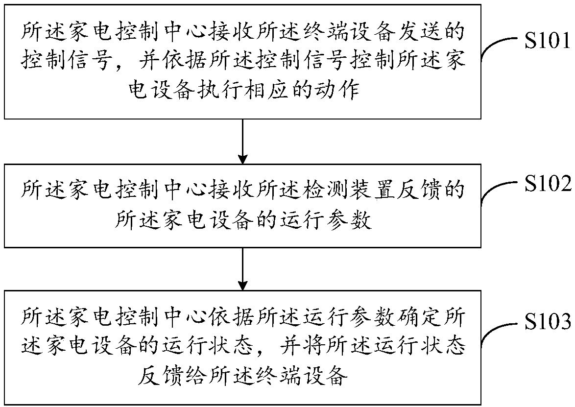
[0045] Please refer to image 3 , Is a schematic flow chart of the smart home detection method provided by the third embodiment of the present invention. The smart home detection method can be applied to the smart home detection system 100 described in the first embodiment. It should be noted that the smart home detection method described in the embodiment of the present invention does not image 3 And the specific sequence described below is a limitation, and its basic principles and technical effects are the same as those of the first embodiment. For a brief description, parts not mentioned in this embodiment are mentioned, and the corresponding content in the first embodiment can be referred to. It should be understood that, in other embodiments, the sequence of some steps of the smart home detection method described in the embodiments of the present invention may be exchanged according to actual needs, or some of the steps may also be omitted or deleted. The following will ...


PUM


Abstract

The invention provides a smart home testing system and a method thereof, wherein the system and the method relate to the technical field of smart home. The system comprises terminal equipment, a household electrical appliance control center and a testing device. The household electrical appliance control center is in communication connection with the terminal equipment, the testing device and thehousehold electrical appliance. The testing device is electrically connected with the household electrical appliance. The household electrical appliance control center receives a control signal whichis transmitted from the terminal equipment, and makes the household electrical appliance perform a corresponding action according to the control signal. The household electrical appliance control center receives an operation parameter of the household electrical appliance, wherein the operation parameter is feed back by the testing device, determines an operation state of the household electricalappliance according to the operation parameter, and performs feedback of the operation state to the terminal equipment. The system determines a fact that the operation state of the household electrical appliance is stopped or in-operation according to whether fluctuation of current data which are fed back from the testing device, and furthermore fed back the operation state of the household electrical appliance to the terminal equipment, thereby confirming whether the household electrical appliance truly performs the corresponding action, and improving user experience.

Description

Technical field [0001] The present invention relates to the technical field of smart homes, in particular to a smart home detection system and method. Background technique [0002] With the improvement of living standards, smart home systems are becoming increasingly popular. Smart home is the use of advanced computer technology, network communication technology, integrated wiring technology, medical electronic technology, according to the principles of ergonomics, fusion of individual needs, the various subsystems related to home life such as security, lighting control, curtain control, gas Valve control, information appliances, scene linkage, floor heating, health care, sanitation and epidemic prevention, security and security are organically combined, and through networked integrated intelligent control and management, it brings people a new home life experience and improves home safety , Convenience, artistry, etc. [0003] In most current smart home systems, infrared technol...

Claims


Application Information

Patent Timeline
IPC IPC(8): G05B15/02G05B19/418
CPCG05B15/02G05B19/418G05B2219/2642
Inventor 黄智全林松华杨明
Owner XIAMEN INTRETECH
Why Eureka
Try Eureka