
Sand tray construction method based on tile terrain modeling and projection correction

A construction method and tile technology, applied in 3D modeling, graphic image conversion, image data processing, etc., can solve the problems of difficult to see the whole picture, long viewing distance, poor experience, etc.

Active Publication Date: 2018-02-16
STATE GRID XINJIANG ELECTRIC POWER +1
View PDF7 Cites 17 Cited by
  • Summary
  • Abstract
  • Description
  • Claims
  • Application Information

AI Technical Summary

Problems solved by technology

But the disadvantage is that most word sand tables are deployed on the horizontal plane, and the area of ​​the projection medium is proportional to the scale of the sand table, that is, the finer the local display requires a larger area of ​​the projection medium, but the larger the area, the farther the viewing distance is, and the harder it is to see the whole picture. It is difficult to coordinate the area of ​​the projected medium, the scale of the sand table and the look and feel
At the same time, because the observer usually watches the sand table at the edge of the screen, the observation field of view forms a oblique viewing cone, and the content of the sand table will form different perspective deformations, which cannot achieve a true three-dimensional look and feel, and the experience is poor.
[0005] The display form of the sand table, the traditional physical sand table is mainly based on a single screen on the ground, and the digital sand table in the market is mostly displayed in the form of a single screen, an L-shaped double screen or an arc screen. The amount of information expressed by these display methods is limited, and because the single screen , L screens and arc screens cannot form a closed space, and cannot bring users an immersive three-dimensional viewing experience

Method used


Image

  • Sand tray construction method based on tile terrain modeling and projection correction
  • Sand tray construction method based on tile terrain modeling and projection correction
  • Sand tray construction method based on tile terrain modeling and projection correction

Examples


Embodiment Construction

[0076] In order to make the object, technical solution and advantages of the present invention clearer, the present invention will be described in further detail below in conjunction with the embodiments and accompanying drawings. Here, the exemplary embodiments and descriptions of the present invention are used to explain the present invention, but not to limit the present invention.

[0077] The purpose of the present invention is to solve the problem of inconsistency between the projected medium area and the sand table display scale of the current digital sand table display, and the problem that there is a squint cone distortion in the three-dimensional scene in the squint state during the edge viewing process, and at the same time improve the single display form of the current digital sand table The disadvantages are to improve the flexibility and display effect of the digital sand table, and provide users with a more vivid and vivid three-dimensional sand table look and ex...


PUM


Abstract

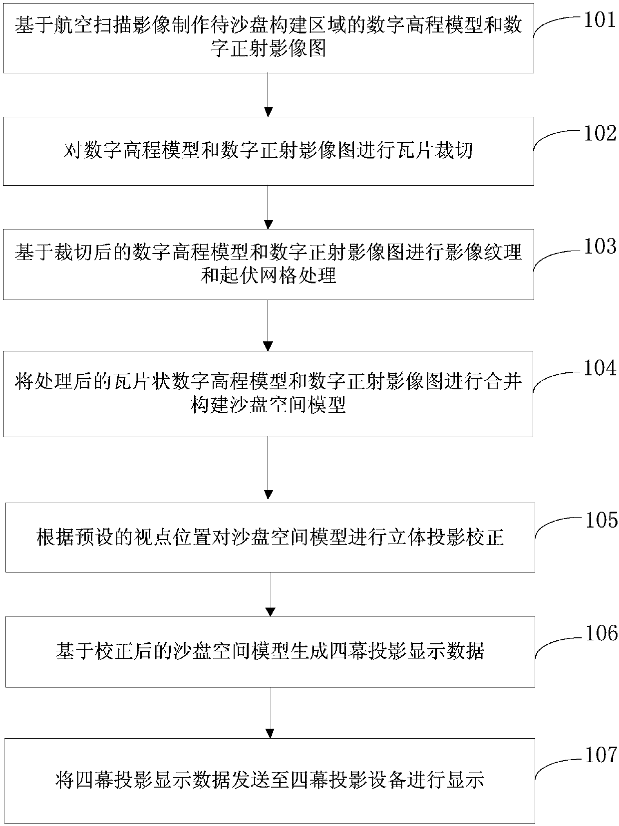
The invention discloses a sand tray construction method based on tile terrain modeling and projection correction. The method comprises the steps that a digital elevation model and a digital orthophotomap of a region where a sand tray is about to be constructed are made; tile clipping is performed on the digital elevation model and the digital orthophoto map; image texture and fluctuating mesh processing is performed based on the digital elevation model and the digital orthophoto map after clipping; the processed tile-like digital elevation model and the processed digital orthophoto map are merged, and a sand tray spatial model is constructed; stereoprojection correction is performed on the sand tray spatial model according to preset viewpoint positions; four-screen projection display datais generated based on the corrected sand tray spatial model; and the four-screen projection display data is sent to four-screen projection equipment for display. Through the method, four projection screens are utilized to construct a digital sand tray display space, the display mode of the digital sand tray is greatly improved, and the view experience of the digital sand tray is greatly improved.

Description

technical field [0001] The invention relates to a sand table construction method based on tile terrain modeling and projection correction, belonging to the field of geographical sand table construction. Background technique [0002] The sand table generates a miniature surface model by simulating the real three-dimensional geographical environment, and intuitively displays the three-dimensional terrain. The current sand table has the following display forms and characteristics: [0003] Traditional physical sand table, that is, using industrial materials such as sediment to pour and accumulate geographical scenes through traditional methods, it expresses topography and landforms in the form of three-dimensional objects, and can reproduce the ups and downs of landforms in a delicate and realistic manner, and can better display The interrelationships and positions between features and landforms are more practical and ornamental than two-dimensional flat maps. However, the di...

Claims


Application Information

Patent Timeline
IPC IPC(8): G06T3/00G06T17/05
CPCG06T17/05G06T3/08
Inventor 刘劲松白伟黄震阿斯卡尔万明忠范光甫戴拥民范卫东孙健刚李凤亮肖少辉刘奎赵宜明汤鸿颂崔永军崔福海张效俊严研陈敬理马旭侯小波任培祥董鉥涛周安吴斌
Owner STATE GRID XINJIANG ELECTRIC POWER
Learn More