
Cable intermediate connector and manufacturing and mounting method therefor

A cable intermediate joint and intermediate joint technology, which is applied in cable joints, equipment for connecting/terminating cables, etc., can solve the problems of poor connection of conductor connecting pipes, imperfect joint sealing and waterproofing, insufficient mechanical strength, etc., to improve adaptability. performance, enhance mechanical protection performance and sealing performance, and ensure the effect of effective contact

Pending Publication Date: 2018-02-16
GUANGZHOU GO LIK CABLE ACCESSORY
View PDF0 Cites 9 Cited by
  • Summary
  • Abstract
  • Description
  • Claims
  • Application Information

AI Technical Summary

Problems solved by technology

[0002] The power cable intermediate joint is an important part of the cable line, but because the cable accessories are multi-layer solid composite dielectric insulation and sealing structure, it is more complicated than the power cable, and it needs to be manually manufactured and installed on site, and the operating conditions are harsh or even soaked in water for a long time , there are a series of problems such as loose connection of the conductor connecting pipe, eccentric connecting pipe, imperfect sealing and waterproofing of the joint, insufficient mechanical strength, etc., resulting in the middle joint of the cable often becoming a weak link in the cable line

Method used


Image

  • Cable intermediate connector and manufacturing and mounting method therefor
  • Cable intermediate connector and manufacturing and mounting method therefor
  • Cable intermediate connector and manufacturing and mounting method therefor

Examples


Embodiment Construction

[0041] The technical solution of the present invention will be further introduced in detail below in conjunction with the accompanying drawings and specific embodiments.

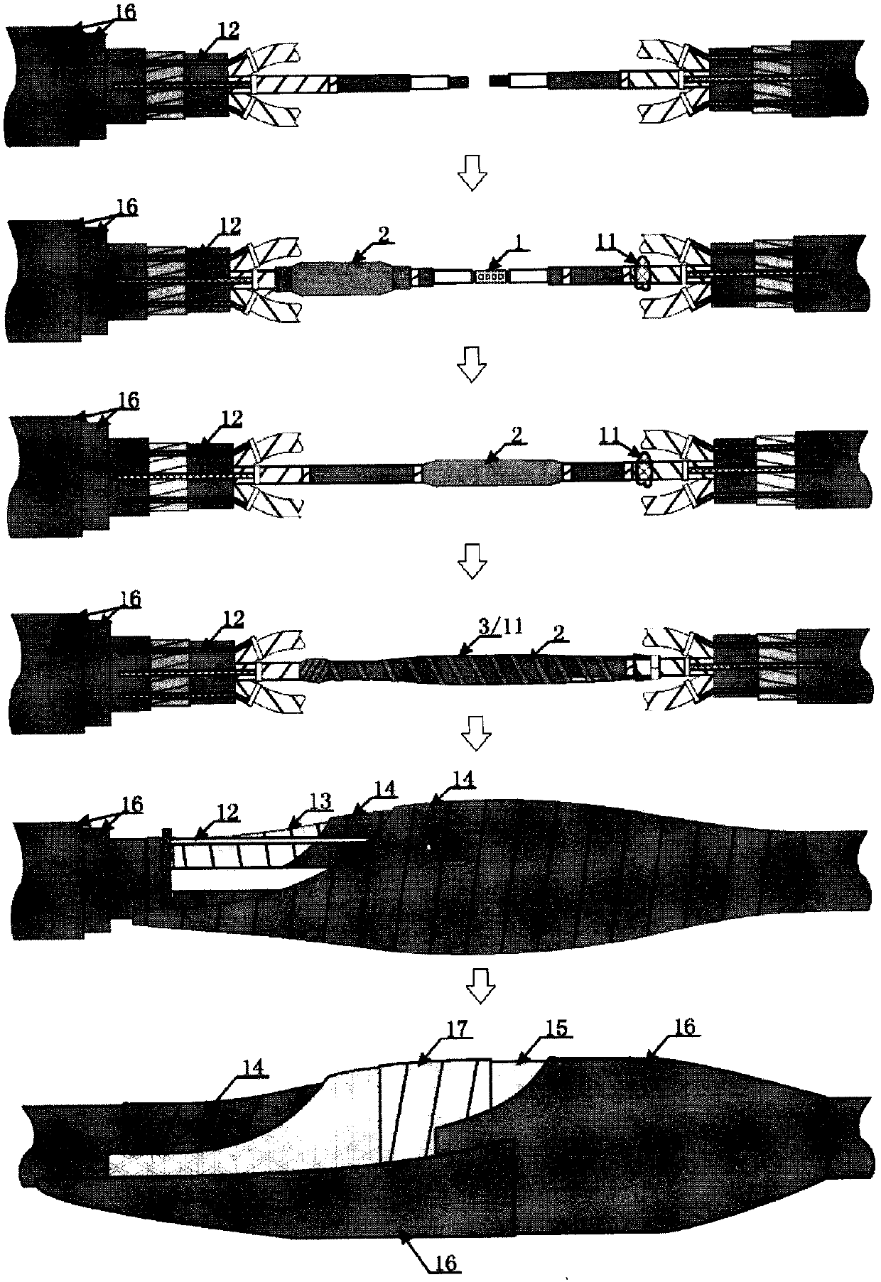
[0042] Such as figure 1 As shown, the present invention provides a cable intermediate joint for connecting three-phase cables of two-circuit power cables. Part 3. Cable inner sheath recovery part 4. Mechanical protection and waterproof sealing part 5, characterized in that:

[0043] The intermediate joint adopts a multi-layer solid composite dielectric insulation and sealing structure.

[0044] The main body 2 of the cold-shrinkable intermediate joint adopts an integrated multi-layer composite structure, including a stress cone 6, an inner shielding layer 7, an insulating layer 8 and an outer shielding layer 9 from the inside to the outside; the main body of the cold-shrinkable intermediate joint each The layers are all made of liquid silicone rubber material, of which the stress cone, the inner and outer ...


PUM


Abstract

The invention relates to a cable intermediate connector used for connecting three-phase cable lines of two power cables. The cable intermediate connector comprises a conductor connector, a cold contraction type intermediate connector main body, a cable shielding layer recovery part, a cable inner sheath layer recovery part and a mechanical protection and waterproof sealing part; the intermediate connector adopts a multilayered solid composite dielectric insulation and sealing structure; the intermediate connector main body adopts an integrated type multilayered composite structure, and comprises a stress cone, an internal shielding layer, an insulating layer and an outer shielding layer from inside to outside, wherein the inner shielding layer and the insulating layer adopt non-equal innerdiameter structures, and the inner diameter of the inner shielding layer is larger than that of the insulating layer; multiple semi-conductive stepped contacts are arranged in the middle position ofthe inner shielding layer; the mechanical protection and waterproof sealing part adopts a half-overlapped and wound armoured band; and the outermost layer is sleeved with a thermal shrinkage pipe anda wrapping thermal shrinkage band. The invention provides the cable intermediate connector which is high in conductor connection, insulating and reliable, high in sealing property, high in mechanicalstrength and simple in structure, and the manufacturing and mounting method for the cable intermediate connector, so that a significant meaning to improvement of safety and reliability levels of the cable circuit is achieved.

Description

technical field [0001] The invention belongs to the technical field of power cables, and relates to a power cable accessory, in particular to a cable intermediate joint and a manufacturing and installing method thereof. Background technique [0002] The power cable intermediate joint is an important part of the cable line, but because the cable accessories are multi-layer solid composite dielectric insulation and sealing structure, it is more complicated than the power cable, and it needs to be manually manufactured and installed on site, and the operating conditions are harsh or even soaked in water for a long time , There are a series of problems such as loose connection of the conductor connecting pipe, eccentric connecting pipe, imperfect sealing and waterproofing of the joint, insufficient mechanical strength, etc., resulting in the cable intermediate joint often becoming a weak link in the cable line. The experience of system operation shows that most of the cable faul...

Claims


Application Information

Patent Timeline
Patent Type & Authority Applications(China)
IPC IPC(8): H02G15/18H02G1/14
CPCH02G1/14H02G15/18
Inventor 陈建斌简咏良岑嘉洛
Owner GUANGZHOU GO LIK CABLE ACCESSORY
Learn More