Electromagnetic heating cooker and control method and control apparatus therefor
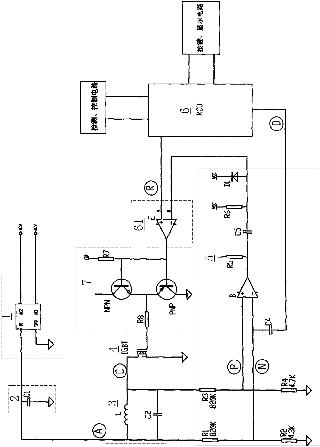
A control method and technology of a control device, which are applied to electric heating devices, induction heating control, induction heating devices, etc., can solve the problems of vibration stop of resonant circuit 3, inversion of comparator E output, heating, etc.
- Summary
- Abstract
- Description
- Claims
- Application Information
AI Technical Summary
Problems solved by technology
Method used
Image
Examples
Embodiment 1
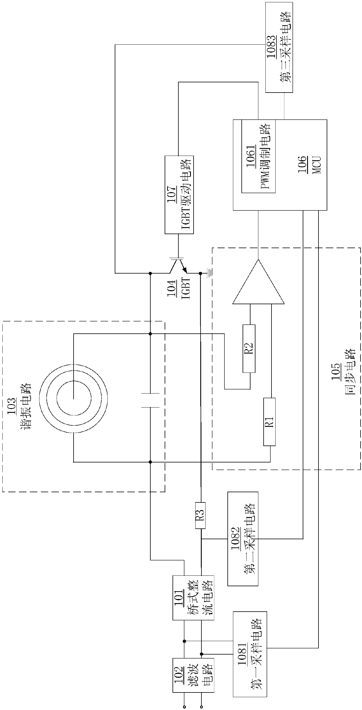
[0046] The electromagnetic oven of this embodiment includes: a resonant circuit and an IGBT, and the IGBT forms an electromagnetic oscillation circuit together with the resonant circuit and an external power supply (commercial power), thereby generating high-frequency magnetic field changes through the mutual cooperation of the coil disk and the capacitor in the resonant circuit , and then form a magnetic field vortex between the induction cooker and the pot, causing the metal atoms in the pot to vibrate, making the pot heat up, and then achieving the purpose of heating the food.
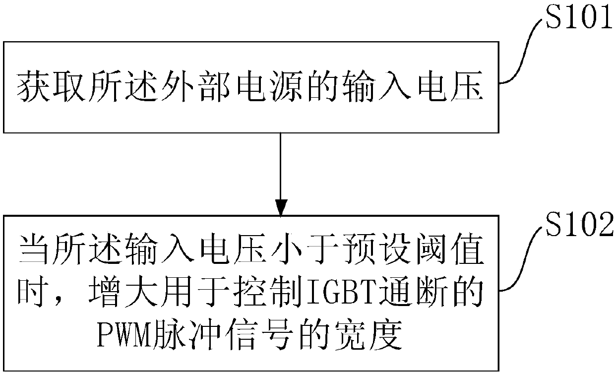
[0047] figure 2 It is a schematic flowchart of the control method provided in this embodiment. Such as figure 2 As shown, the control method of the present embodiment includes:
[0048] S101. Obtain an input voltage of the external power supply.
[0049] In the actual environment, obtaining the input voltage of the external power supply can be realized through various methods. for example:
...
Embodiment 2
[0074] The electromagnetic oven of this embodiment includes: a resonant circuit and an IGBT, and the IGBT forms an electromagnetic oscillation circuit together with the resonant circuit and an external power supply (commercial power), thereby generating high-frequency magnetic field changes through the mutual cooperation of the coil disk and the capacitor in the resonant circuit , and then form a magnetic field vortex between the induction cooker and the pot, causing the metal atoms in the pot to vibrate, making the pot heat up, and then achieving the purpose of heating the food.
[0075] Figure 4 A schematic structural diagram of the control device 200 provided in this embodiment. Such as Figure 4 As shown, the control device 200 of this embodiment can execute the control method of the first embodiment, which includes: a first sampling module 202 , and a processing module 201 electrically connected to the first sampling module 202 . Wherein, the first processing module 20...
Embodiment 3
[0089] The electromagnetic oven of this embodiment includes: a resonant circuit and an IGBT, the IGBT forms an electromagnetic oscillation circuit together with the resonant circuit and an external power supply (commercial power), thereby generating high-frequency magnetic field changes through the mutual cooperation of the coil disk and the capacitor in the resonant circuit , and then form a magnetic field vortex between the induction cooker and the pot, causing the metal atoms in the pot to vibrate, making the pot heat up, and then achieving the purpose of heating the food.
[0090] Figure 5 A schematic structural diagram of the control device 300 provided in this embodiment. Such as Figure 5 As shown, the control device 300 of this embodiment includes: a memory 302 storing an executable instruction set, and a processor 301 . Wherein, the processor 301 is configured to call the executable instruction set in the memory 302 to execute the control method in the first embodi...
PUM
 Abstract
Description
Claims
Application Information
 - R&D
- Intellectual Property
- Life Sciences
- Materials
- Tech Scout
- Unparalleled Data Quality
- Higher Quality Content
- 60% Fewer Hallucinations
Browse by: Latest US Patents, China's latest patents, Technical Efficacy Thesaurus, Application Domain, Technology Topic, Popular Technical Reports.
© 2025 PatSnap. All rights reserved.Legal|Privacy policy|Modern Slavery Act Transparency Statement|Sitemap|About US| Contact US: help@patsnap.com


