Plant Diagnosis Device And Plant Diagnosis Method

A technology of factory equipment and diagnostic devices, applied in the direction of instruments, manufacturing computing systems, data processing applications, etc.

Active Publication Date: 2018-02-16
HITACHI LTD
View PDF17 Cites 4 Cited by
  • Summary
  • Abstract
  • Description
  • Claims
  • Application Information

AI Technical Summary

Problems solved by technology

Call this parameter the resolution parameter

Method used


Image

  • Plant Diagnosis Device And Plant Diagnosis Method
  • Plant Diagnosis Device And Plant Diagnosis Method
  • Plant Diagnosis Device And Plant Diagnosis Method

Examples


Embodiment 1

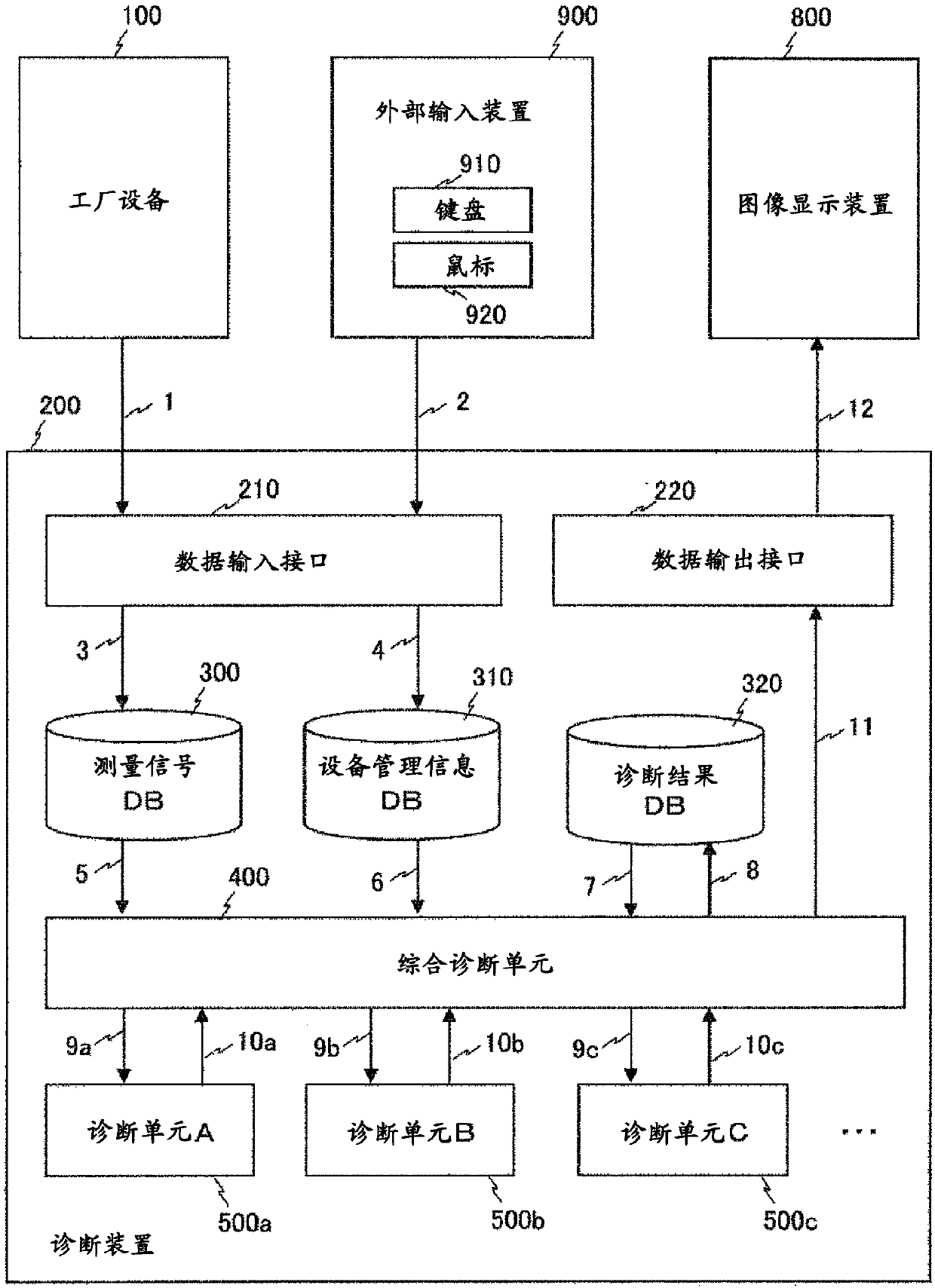
[0037] figure 1 It is a block diagram illustrating a diagnostic device as a first embodiment of the present invention. The diagnostic device 200 is connected to the factory equipment 100 , the image display device 800 , and the external input device 900 , and monitors and diagnoses the factory equipment 100 . In addition, the diagnostic device 200 is configured to connect a communication unit, a computer, a computer server (CPU: Central Processing Unit), a memory, various databases DB, etc., which perform communication between devices or devices, in a wired or wireless manner. . In addition, the external input device 900 is constituted by a keyboard switch, a pointing device such as a mouse, a touch panel, an audio pointing device, and the like, and the image display device 800 is composed of a liquid crystal display or the like.

[0038] Diagnostic device 200 includes comprehensive diagnostic unit 400 and diagnostic unit 500 as computing devices. There are multiple diagnos...

Embodiment 2

[0156] In Embodiment 2 of the present invention, a case where model diagnosis and clustering are applied as the diagnosis technique 500 will be described. The technique described in Example 1 was applied with respect to clustering.

[0157] Figure 13 is a diagram illustrating model diagnosis. In the model diagnosis, a machine model simulating characteristics of machines constituting the factory equipment 100 is used. As a method of constructing a model simulating the factory equipment 100, there are physical models using physical formulas such as mass conservation formulas and heat transfer formulas, and statistical models such as neural networks, and Japanese Patent Application Laid-Open No. 2006-57595 is a disclosed technique.

[0158] The input / output information of the machines constituting the factory equipment 100 are measured as a signal A and a signal B, respectively. In the machine model, the output is the predicted value of signal B with respect to the input of s...

Embodiment 3

[0167] Effects when the diagnostic device 200 of the present invention is applied to C / C factory equipment will be described.

[0168] Figure 15 It is a figure which shows the machine structure of the C / C plant which is an Example of the plant 1000. The gas turbine 1080 is composed of a compressor 1010 , an expander 1020 , and a combustor 1030 . In the gas turbine 1080, the compressor 1010 takes in air and compresses it, and then the combustor 1030 takes in the compressed air and fuel and generates combustion gas, and the expander 1020 takes in the combustion gas and obtains power. The output of the gas turbine 1080 is the difference between the power output by the expander 1020 and the power used by the compressor 1010 . A heat exchanger 1060 is arranged in the waste heat recovery boiler 1050 , and high-temperature steam is generated using high-temperature exhaust gas from a gas turbine 1080 . In the steam turbine 1070, the high-temperature steam generated by the waste he...


PUM


Abstract

When an abnormality is detected, a decision about whether or not the abnormality should be dealt with is made based onon the basis of experiences in operating a plant. However, it is preferable to make the decision on the basis ofbased on a risk (expected loss amount) that would occur when if the abnormality iswere to be left as is. In order to achieve this, the present invention is a plant diagnosis device equipped with multiple diagnosis means for diagnosing an abnormality state of the plant, and characterized by being equipped with a comprehensive diagnosis means that, upon determining degrees of accuracy in detecting the abnormal states with respect to each of the multiple diagnosis means on the basis of measurement signal data pertaining to plant states and facility management information data pertaining to past abnormal states, evaluates expected loss amounts on the basis of the degrees of accuracy and loss amounts associated with the abnormal states.

Description

technical field [0001] The present invention relates to a plant equipment diagnosis device and a plant equipment diagnosis method for diagnosing an abnormal state of plant equipment. Background technique [0002] When an abnormal transient phenomenon or an accident occurs in the factory equipment, the factory equipment diagnosis device detects the occurrence of the abnormality or the accident based on the measurement data from the factory equipment. [0003] Patent Document 1 discloses a diagnostic device applying Adaptive Resonance Theory (ART), which is one of clustering techniques. Here, the so-called ART is a theory for classifying multidimensional data into different categories according to their similarities. [0004] In the technique described above, first, the measurement data at normal times are classified into a plurality of categories (normal categories) by ART. Then, the current measurement data is fed into ART and sorted into different categories. When the me...

Claims


Application Information

Patent Timeline
Patent Type & Authority Applications(China)
IPC IPC(8): G05B23/02G06Q50/04G06Q50/10
CPCG05B23/02G06Q50/04G06Q50/10Y02P90/30
Inventor 关合孝朗林喜治前田达矢定江和贵村上正博深井雅之
Owner HITACHI LTD
Why Eureka
Try Eureka