
Syringe

A technology of syringes and push rods, which is applied in the field of syringes, and can solve problems such as the deformation of the syringe barrel, the danger of surgery, and the occurrence of medical accidents, so as to avoid backflow, facilitate production and processing, and reduce medical accidents.

Pending Publication Date: 2018-02-23
BEIJING CHUNLIZHENGDA MEDICAL INSTR
View PDF0 Cites 2 Cited by
  • Summary
  • Abstract
  • Description
  • Claims
  • Application Information

AI Technical Summary

Problems solved by technology

[0003] However, in the process of taking bone marrow fluid, the operation process of the syringe is different from the extraction of ordinary liquids (such as blood and medicinal liquid, etc.), and a large negative pressure will be generated in the syringe barrel during the operation. Due to its material and strength, the syringe barrel is easily deformed under high negative pressure, which eventually leads to failure of extraction
In addition, because there is no locking device in the existing syringe, for example, during the extraction process, it cannot be ensured that the syringe push rod is pulled towards the end of the injection cylinder, but moves in the opposite direction, which will cause the extracted bone marrow fluid to be lost unexpectedly. Unconsciously retreat to the human body, which will make the operation dangerous or even cause medical accidents
[0004] Aiming at the deficiencies of the prior art, those skilled in the art hope to find a syringe that can position the syringe push rod on the syringe barrel at any time during the extraction process, so as to ensure the accuracy of the operation during the clinical process and reduce the medical malpractice

Method used


Image

  • Syringe
  • Syringe
  • Syringe

Examples


Embodiment Construction

[0026] Embodiments of the technical solutions of the present invention will be described in detail below in conjunction with the accompanying drawings. The following examples are only used to illustrate the technical solutions of the present invention more clearly, and therefore are only examples, rather than limiting the protection scope of the present invention.

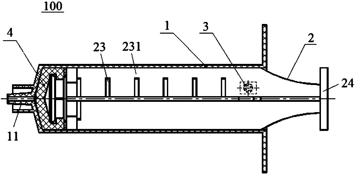
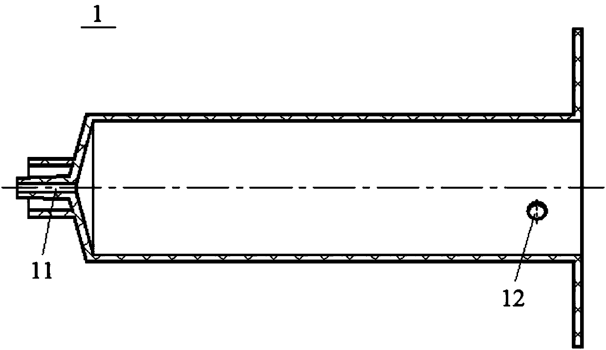
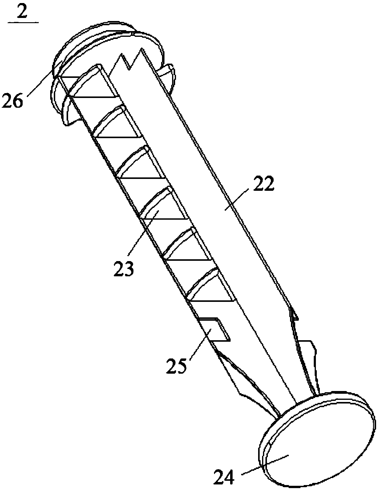
[0027] figure 1 A schematic structural view of the syringe 100 according to the present invention is shown. like figure 1 As shown, the syringe 100 includes: a cylinder body 1, and a fixing hole 12 is formed on the peripheral wall of the end of the cylinder body 1 (eg figure 2 As shown), the head end of the barrel 1 is formed with a needle joint 11 (the needle joint 11 is preferably a Luer joint); a push rod 2, the push rod 2 can reciprocate relative to the inner wall of the barrel 1; and a positioning stopper 3. The positioning block 3 can be inserted and fixed in the fixing hole 12 . which, combined with F...


PUM


Abstract

The invention relates to the field of medical instruments, and discloses a syringe which comprises a cylinder, a push rod and a positioning stopper. A fixing hole is formed in the peripheral wall of the tail end of the cylinder, the push rod can reciprocate relative to the inner wall of the cylinder, the positioning stopper can be fixedly inserted into the fixing hole, the push rod comprises a rodbody and at least two ribs formed on the peripheral wall of the rod body at intervals, the ribs axially extend along the rod body, a partition piece is formed on at least one rib and extends towardsanother rib adjacent to the rib, an opening is formed between an extending end of the partition piece and the adjacent rib, and the positioning stopper passes the opening. According to the syringe, the push rod can be positioned on the cylinder in the extraction process at any time and can be effectively prevented from moving towards the head end of the cylinder, backflow of extracted liquid can be avoided, and medical accidents caused by misoperation are further effectively reduced.

Description

technical field [0001] The invention relates to the field of medical devices, in particular to a syringe. Background technique [0002] Bone marrow aspiration is a common diagnostic technique for collecting bone marrow fluid, which is usually collected with a syringe during the operation. Existing syringes used in bone marrow aspiration are syringes of common structure, which generally include a syringe barrel, a syringe push rod and a syringe piston. Wherein, the front end of the syringe barrel adopts a Luer connector capable of holding a needle, and the front end of the syringe push rod is provided with a syringe piston, and the syringe push rod moves relative to the syringe barrel under the action of external force to drive the reciprocating movement of the syringe piston, thereby Realize the function of syringe extraction or injection. [0003] However, in the process of taking bone marrow fluid, the operation process of the syringe is different from the extraction of ...

Claims


Application Information

Patent Timeline
IPC IPC(8): A61B10/02
CPCA61B10/025A61B10/0283A61B2010/009
Inventor 史春宝许保全宋杰解凤宝
Owner BEIJING CHUNLIZHENGDA MEDICAL INSTR
Learn More