Detachable electromagnetic edge-pressing drawing die and control method for edge-pressing force of detachable electromagnetic edge-pressing drawing die

A technology for deep drawing dies and control methods, applied in electrical program control, program control in sequence/logic controllers, forming tools, etc., can solve problems such as the inability to remove the influence of mechanical pressure on blank holder force, and achieve compact structure , flexible and precise adjustment, and easy maintenance

Pending Publication Date: 2018-02-23
UNIV OF JINAN
View PDF0 Cites 8 Cited by
  • Summary
  • Abstract
  • Description
  • Claims
  • Application Information

AI Technical Summary

Problems solved by technology

[0004] The purpose of the present invention is to solve the vacancy of the existing blank holder technology, and provide a detachable electromagnetic blank holder thin plate drawing die and its control method for blank holder force, which can adjust the controllable DC power supply to Realize variable blank holder force output, and solve the problem that the existing electromagnetic blank holder deep drawing mold cannot remove the influence of mechanical pressure on blank holder force, and propose a detachable mold structure

Method used


Image

  • Detachable electromagnetic edge-pressing drawing die and control method for edge-pressing force of detachable electromagnetic edge-pressing drawing die
  • Detachable electromagnetic edge-pressing drawing die and control method for edge-pressing force of detachable electromagnetic edge-pressing drawing die
  • Detachable electromagnetic edge-pressing drawing die and control method for edge-pressing force of detachable electromagnetic edge-pressing drawing die

Examples


Embodiment Construction

[0029] In order to have a clearer understanding of the technical features, purposes and effects of the present invention, the specific implementation of the present invention will now be described with reference to the accompanying drawings, but it is only a preferred embodiment and is not used to limit the essential scope of the present invention.

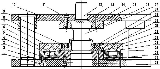
[0030] figure 1 It is a schematic diagram of the mold structure of the present invention, and the detachable electromagnetic clamping device includes a set screw 1, an upper mold base 2, an adjusting gasket 3, a guide post 4, a fixing ring 5, an electromagnetic coil 6, and a die 7, Set screw 8, die sleeve 9, upper die holder 10, set screw 11, die handle 12, positioning pin 13, cylindrical pin 14, backing plate 15, punch fixing plate 16, punch 17, blank holder ring 18, Connecting plate 19, magnetic ring 20, sheet material 21, limit plate 22, set screw 23, set screw 24, magnetic isolation plate 25, cylindrical pin 26, cylindrical pi...


PUM


Abstract

The invention discloses a detachable electromagnetic edge-pressing drawing die and a control method for edge-pressing force. The detachable electromagnetic edge-pressing drawing die comprises a platedrawing system, an electromagnetic edge-pressing system and an excitation current control system. A female die body in the die is fixed to a lower die seat through fastening screws; a plate is placedin a groove of a limiting plate; a male die body adopts a ladder form, and the male die body, a male die fixing plate and a male die cushion plate are fastened on an upper die seat through fastening screws; and a combined edge-pressing ring is composed of a detachable connecting plate and an edge-pressing ring body. The combined edge-pressing ring is matched with a magnetic ring and fastened by aninner set of fastening bolts and an outer set of fastening bolts which are distributed in a staggered mode in the circumferential direction. An overlap joint connector matched with the combined edge-pressing ring is formed in the inner edge of a magnetic guide ring, and a groove is formed in the upper end face of a fixed ring to store an electromagnetic coil. Accurate control over an excitation current in the electromagnetic coil is achieved in the mode that a designed controllable direct current power supply is adopted to provide the adjustable excitation current to the electromagnetic coil.According to the drawing die, the precise controllable edge-pressing force can be exerted on the flange part of the plate in the drawing process, the connecting plate is detachable, thus the die canbe conveniently replaced, switching response of the electromagnetic force and the edge-pressing force is quick, the production cost can further be reduced, and the production efficiency is improved.

Description

technical field [0001] The invention relates to a detachable electromagnetic blank-holding deep drawing die and a blank-holding force control method thereof, in particular to a forming die suitable for sheet metal deep drawing. Background technique [0002] During the deep drawing process of the thin plate, a large tensile stress will be generated in the radial direction at the blank flange, and a large compressive stress will be generated in the tangential direction, which is easy to cause wrinkling defects. Usually, applying blank-holding force at the blank flange can effectively suppress flange wrinkling defects, so the precise control of blank-holding force is one of the key technologies to determine the quality of sheet metal forming. There are two types of common edge-holding methods: mechanical and hydraulic edge-holding. Mechanical crimping mainly uses springs, rubber pads and nitrogen cylinders, while hydraulic crimping is realized by the liquid pressure generated ...

Claims


Application Information

Patent Timeline
IPC IPC(8): B21D37/10B21D22/22G05B19/04
CPCG05B19/04B21D22/22B21D37/10
Inventor 王强李昊何芳郑娅云
Owner UNIV OF JINAN
Why Eureka
Try Eureka